The Heybridge Railway, 1889 to 1913

Richard Gawler

Western Thunderer
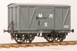
I have given the model the mildest of refurbishments - I have removed the surface rust, blackened the buffers, darkened the wheels, and fixed the loose parts.

DSC_6158.jpeg

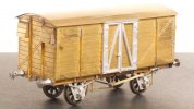
The model represents a van built to Diagram 360, fitted for working in express passenger trains but without a through steam pipe, and there is a detailed discussion of the livery here. The source would have been Slater's kit number 7024.
 

Richard Gawler

Western Thunderer
If it was being used for delivering forged track spikes from the Black Country, could one say it was conveying the staple traffic of the Heybridge Railway?

This quote is too good to leave behind elsewhere :D

Unfortunately, such a large consignment of track spikes to an existing railway raises problems with logic unless of course they were for the proposed Goldhanger Extension to the line which rattles around in my mind from time to time but which, perhaps mercifully, hasn’t yet made it into WT in any detail.

We know Heybridge Basin handled imports of timber from Scandinavia. I haven’t found out about a return traffic, so I suggest this van is carrying woollen garments made in North-West England and destined for export to Scandinavia. Transhipment being at Heybridge Basin. The use of a fitted van may be simply because this is what was available; or because the shipments need a “just in time” service to tie in with irregular sailings.

I will try to remember to make some spare spikes, to put in my PW wagon :)
 
GER 10 ton van (1910) - buffers and completion

Richard Gawler

Western Thunderer
DSC_3869.jpeg

So this is how the model will look for a while, posed here between my Peco/Parkside NB van and my Three Aitch MR van. I have built this GER van entirely from the kit, except for the copper wire between the brake hangers (I had to destroy the piece supplied in the kit during a rebuild of the brake gear) and of course the Slater's wheels.

Six months after I first put my GER 10 ton van onto the track I have tracked down some suitable buffers.

DSC_6222.jpeg
These are GER wagon buffers from Haywood Railway. They are an upgrade from the cast white metal ones supplied in the kit, and I think worthwhile.

The axlebox further from the camera is filled flush with epoxy glue but this dries clear. This model is probably structurally complete and ready for painting now.
 
Rebalancing the Wagon Fleet New

Richard Gawler

Western Thunderer
Isn’t Brymbo a bit out of area for your railway?

The balance will get better as I build more wagons for businesses in Essex and neighbouring counties.

I have done a little re-balancing of my wagon fleet. The Brymbo wagon jars in my mind. I am pleased with the brake gear but somehow, the combination of unprotypical model and distant operator seems that bit too wrong. I would probably keep it if it was a better model or a more local owner. At least I know what I did to the brakes, the photos are on WT, and I could do similar rebuilds to different models.

I said goodbye to my GWR Hydra a while ago. This was a scale model and suitable but I couldn't devise a sensible load for it to bring to the Heybridge Railway. So I suppose I am doing fairly well if I have built 14 wagons and only let go of one.

I bought some 9ft sleepers from a modeller in Devon and discovered he wanted to downsize his GER collection. So I could hardly resist these . . .

DSC_6512.jpeg

DSC_6508.jpeg
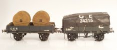
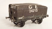
According to Tatlow (LNER wagons vol.1 p.188), the GER built 3,000 four- and later five-plank wagons to diagram 16 during the decade to 1895. So this model fits my the layout perfectly. I have a Mystery Load too, if I try using playing cards for operations.

DSC_6509.jpeg
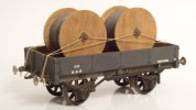
I don't know about the drop side wagon yet. Studying Tatlow, it looks as though these didn't make it into the LNER. But drums of electric cable could be making their way to Bentall's factory or, via the navigation to Chelmsford.

The GER painted these wagons slate grey and this is usefully different to the greys of the wagons belonging to the Heybridge Railway. Thank you Peter.

As far as rebalancing goes, I now have three GWR wagons instead of four, and three GER wagons instead of one, and I have gained two absolutely beautiful models to do this. Good.
 
Standards for Building Plain Track New

Richard Gawler

Western Thunderer
I have had a go at making some flat bottom track using code 100 rail from Kalgarin and 9 ft sleepers from C&L. This was a trial to find out how much the appearance would differ from Peco’s bullhead flexi track, and to end up with something to stand my Y14 on inside its display case.

View attachment 207552
This is the first time I have used graph paper for years. The sleeper pitch of 7/10ths inch represents a scale 30.5 inches. The code 100 rail is representing 60 to 70 lb/yard prototype.

The gauge is the wanted 31.5 mm at one end and almost 32 mm at the other end because I made an effort to hold the rails down onto the sleepers but no effort at all to push them sideways against the gauges. I cannot see the difference.

View attachment 207553
I would have rather have no spikes than overscale spikes but I am still searching for something reasonable.

View attachment 207551
So, a marked difference with the flexi track. There isn’t any comparison really.

Now, I bought the code 100 rail because I thought (and still think) it looks reasonable under a Y14. It is the largest rail section I want for my layout, though I accept it may not really be strong enough for a Y14. Thanks to Col. (@Eastsidepilot) for his recent note on the relaying of the Middy. Hopefully, running at low speeds won't look out of place. I do think, the 2ft 6in sleeper spacing with this rail has a pleasing aesthetic; it looks “light”.

What I really do need to find out is, how to build this track so I can fix it down onto a baseboard and ballast it without the rails popping off during expansion and contraction. If the layout goes in a car in Winter and the hobby room in Summer then I am looking at a temperature variation of 0 to 30 degrees C.

Perhaps scale 40 ft lengths would be sensible for the rails. Perhaps, all I need to do is secure the sleepers below the rail joints and ballast using a latex-based glue. Perhaps, it would be best to leave the rails as long as I can and spike them all down. Any guidance here would be very welcome.

I have put the sample into the display case, it doesn’t photograph very well in there but it looks much better than its predecessor.

Michael thank you so much for all these notes.

I have just found out (from Four Types of Rail Spikes), a modern spike is 16 mm thick. This equates to 15 thou in 7mm scale, while my 26/6 staples measure 18 x 16 thou. So I will stay with these. I have a household stock of several thousand.

I have two BH turnouts for my first diorama, so if I use these then I need to build only plain track to begin with. This is for the traverser and its headshunt. I have limited space for a layout, so I want to make the fiddle yard look as nice as I can. Maybe, even good enough for model photography.

We discussed spiked track earlier; these two posts mark the start and the end of the posts.

I now have a copy of Peter Paye's book, "The Mid-Suffolk Light Railway" (Wild Swan 1986, reprinted 2003) and this work contains many photographs of the original track at the Middy. Now, I know that these photographs were not taken to record the way all of this track was laid; nor were they taken for the railway modeller. But they do repeatedly show one spike not two on each side of the rails, and rail joints on top of sleepers.

The photograph of Mendlesham Station posted by @Rob R is annoyingly clearer than many photos in Paye's book, but I am still wanting to think, the use of a second spike seen here was done to reinforce things or to realign them, and not as a routine practice. The additional spikes seem to be dotted around without any clear pattern.

The Middy was laid with 56 lb/yard rail and I am using code 100 rail which can represent 60 to 70 lb rail. I could claim my rail represents 56 lb/yard rail and this was a (fictional) precursor to the standard adopted by the Middy; but it is easier to leave this one open for now. After all, the Heybridge Railway does see a GER Y14, which would want a heavier rail to reduce the likelihood of breakages.

The photographs in Paye's book suggest a spacing of about 20 inches between sleepers; a sleeper is 10 inches wide so the pitch would be 30 inches. This is the spacing I chose for my example track on "Heybridge Basin", because I thought it looked about right.

So . . . I can go for one spike on each side of the rail on each sleeper for the Heybridge Railway. The Board of Trade may well have been unhappy about this, but if so it is easier to write a fictional letter from them to the railway than to double my workload for building the track. The sleeper pitch can stay at 17 to 18 mm (30 inches), and the rail will be code 100.

Or, to put things more succinctly, "my railway my rules"!

I am happier to firm up on things like this because I now know what I need to do for rest of the track. The only big unknown remaining is what the pointwork should look like, and I don't need to know this until after I build the fiddle yard, complete the Heybridge Basin project, and start thinking about a layout for Heybridge itself.
 

Overseer

Western Thunderer
We discussed spiked track earlier; these two posts mark the start and the end of the posts.

I now have a copy of Peter Paye's book, "The Mid-Suffolk Light Railway" (Wild Swan 1986, reprinted 2003) and this work contains many photographs of the original track at the Middy. Now, I know that these photographs were not taken to record the way all of this track was laid; nor were they taken for the railway modeller. But they do repeatedly show one spike not two on each side of the rails, and rail joints on top of sleepers.

The photograph of Mendlesham Station posted by @Rob R is annoyingly clearer than many photos in Paye's book, but I am still wanting to think, the use of a second spike seen here was done to reinforce things or to realign them, and not as a routine practice. The additional spikes seem to be dotted around without any clear pattern.

The Middy was laid with 56 lb/yard rail and I am using code 100 rail which can represent 60 to 70 lb rail. I could claim my rail represents 56 lb/yard rail and this was a (fictional) precursor to the standard adopted by the Middy; but it is easier to leave this one open for now. After all, the Heybridge Railway does see a GER Y14, which would want a heavier rail to reduce the likelihood of breakages.

The photographs in Paye's book suggest a spacing of about 20 inches between sleepers; a sleeper is 10 inches wide so the pitch would be 30 inches. This is the spacing I chose for my example track on "Heybridge Basin", because I thought it looked about right.

So . . . I can go for one spike on each side of the rail on each sleeper for the Heybridge Railway. The Board of Trade may well have been unhappy about this, but if so it is easier to write a fictional letter from them to the railway than to double my workload for building the track. The sleeper pitch can stay at 17 to 18 mm (30 inches), and the rail will be code 100.

Or, to put things more succinctly, "my railway my rules"!

I am happier to firm up on things like this because I now know what I need to do for rest of the track. The only big unknown remaining is what the pointwork should look like, and I don't need to know this until after I build the fiddle yard, complete the Heybridge Basin project, and start thinking about a layout for Heybridge itself.
A single spike each side of the rail would be normal for 56-60lb track using imported hardwood sleepers such as Jarrah - very common in the UK. If the sleepers were pine extra spikes would help keep the track together as pine doesn’t grip the spikes well. Pine sleepers would usually be placed closer together to carry the same load. 30 inch sleeper centres would be common on light lines but the sleepers could be 8 or 9 inches wide. 10 inch wide Jarrah sleepers would be overkill on a light line, although if they were available at the right price the would have been used.
 
Top