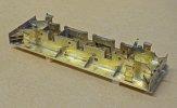
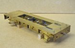
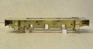
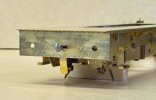
MOVING COAL - A Colliery Layout in 0 Gauge

J Whit

New Member
I've decided to press on with the second Austerity and get it up to the same stage as the first, then worry about all the extra details required for the two locos together. This one will be the Giesl ejector version as Hunslet 3823/54 named WARRIOR, running on the Walkden Railway between 1967 (when it received the Giesl ejector) and the line's closure in October 1970.


The basic chassis was completed some time ago (3½ years - Blimey !) so the first job was to set the front and rear axleboxes to the correct height on the 12BA screws as on the first loco (Post #107). All the axleboxes are numbered with pop marks so they all go back in the same positions.


View attachment 182827

A 3/16" reamer was run through the axle holes by hand to make sure the holes lined up correctly.


View attachment 182828

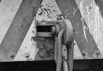
There are two differences in the rear buffer beam from the first loco. A plate hangs vertically down from the centre of the buffer beam and this was to protect the underfeed stoker pipework from damage by the coupling chain swinging forward. The coupling hook is located in a slot giving some sideways movement instead of directly into the buffer beam. This was because the hook was extended when the loco was fitted with the extended bunker and extensions to the buffers (see Post #27 for details). It was shortened back to normal length when the bunker extension was removed. I've fixed the hook in position as it didn't think it actually needed any sideways movement.


After preservation on the Dean Forest Railway in 1986 showing the revised coupling arrangement. The vertical plate below the buffer beam was removed at the same time as the underfeed stoker before the loco was sent from Walkden to Bickershaw Colliery. However the bunker still retains the small sliding door fitted to underfeed stoker locos, probably for access in case of a blockage in the stoker inlet at the bottom of the bunker. Note the larger than normal buffer heads. For some reason Austerities sent to Bickershaw Colliery had larger diameter buffer heads fitted to the rear of the loco.

tbc
Your comments about the sliding door have finally answered something i have wondered about for years , as Repulse used to have the same arrangement , now recently removed as a new bunker being fitted , thankyou , so this leads to a question , were all the stoker fitted engines so equipped ?
 

PhilH

Western Thunderer
Your comments about the sliding door have finally answered something i have wondered about for years , as Repulse used to have the same arrangement , now recently removed as a new bunker being fitted , thankyou , so this leads to a question , were all the stoker fitted engines so equipped ?

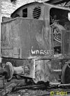
No, REPULSE and WARRIOR were the only two Walkden stoker fitted locos with the sliding door in the standard bunker, the other three fitted with the Hunslet stoker/Giesel arrangement - STANLEY, RESPITE and REVENGE - didn't have the door, neither did the three fitted with the full Hunslet system - FRED, WASP and HURRICANE. However WARSPITE which was fitted with the diesel powered stoker and retained the extended bunker to the end did have the door. (the extended bunkers on any of the other locos were removed before the stokers were fitted).


25113B © PGH.jpg

A rather bent and battered WARSPITE in the shed at Ladysmith in July 1976, about 3 months before it was scrapped.​
 
Last edited:

PhilH

Western Thunderer
39 37712B.jpg

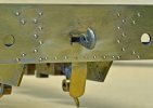
On the prototype the plate hanging down below the rear buffer beam was fixed with two bolts replacing the rivets in the bottom row.
(second one hidden behind the coupling)


40 Bolts.jpg

So as I'd already provided the rivets, I had to drill these out and replace them by pins with the heads filed to hexagonal shape to represent the bolts. They're only just over 0.7mm in size across the flats.
 

PhilH

Western Thunderer
41 WARRIOR Chassis.jpg

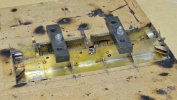
The footplate was soldered to the frames with the two clamped upside down to a piece of MDF. Evidence of past use of the MDF with a blowlamp, although not this time.


42 WARRIOR Chassis B.jpg

The steps and footplate valance were added, the latter from 1.5mm square brass. Plenty of visible solder here ! - I like a nice fillet each side of any joint and spend many happy (?) hours carving away the excess :rolleyes:


43 WARRIOR Chassis B.jpg

The lamp irons and angles for each side of the smokebox were fitted prior to fixing the footplate to the frames and required hollows in the MDF. The grab handles were fitted after, and as mentioned earlier these Austerities were unusual in having two above the front steps instead of the normal one.


44 WARRIOR Chassis B.jpg


45 WARRIOR Chassis B.jpg

The strip at the top of the rear buffer beam represents the vertical part of an angle under the bunker, the horizontal part being just an extension of the footplate. It was an etching with the holes marked as half etched hollows for drilling, and the rivets and bolts are pins with the heads shaped to various sizes. They were soldered in place at the rear with a slight countersink in the strip and then cut off flush, then the strip was soldered to the buffer beam and fortunately they all stayed in position.
Its surprising what you miss in the thing itself but stands out a mile in photos - the top step on the right needs bending down a bit and possibly the bottom step also needs a touch. The bottom step on the left needs bending up a touch.

tbc
 
Last edited:

PhilH

Western Thunderer
Then there were two......or maybe one and a half ?


46 Both Locos 001B.jpg

The 3D 'upperworks' on the second loco just plonked in place, with no finishing work yet apart from the chimney. I soldered the buffers on this time, and nothing dropped off despite having to re-solder a couple a few times to get the damn things straight. Surrounding bits which may have dropped off or moved were retained by various means including Kapton tape. I've found that a permanent marker pen is useful as a solder resist, preventing solder from straying where you don't want it. Its easily removed after with nail varnish remover (acetone).
Its nice when things go as planned, its such a rare event !


47 Both Locos 002B.jpg

No.2 on the left riding a little higher due to less weight on the springs.


48 Coupling Rods.jpg

I used 10BA screws for the crank pins this time instead of 12BA mainly because I didn't have the right length 12BA countersink screws, but I think they are nearer to the prototype crank pin diameter. They are tapped into the nylon wheel centre with the countersink head at the back and then the brass bushes provided by Slaters are also tapped 10BA. The 12BA retaining nuts which were drilled and tapped 10BA are temporary and will be replaced with slightly larger diameter collars.
Next the cab, I have to try to remember just how I put the previous one together :rolleyes:
 

PhilH

Western Thunderer
FRANCIS x 2 001B.jpg

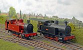
Friend Dave brought his modified Minerva Victory 0-6-0T for a run on the layout and it made an interesting contrast with my scratchbuilt model of the same loco. Mine represents the loco as running in the late 1950s/early 1960s while Dave's represents the loco after fitting with a Giesl Ejector and painting in the red livery in 1966.


FRANCIS x 2 003B.jpg
 

PaulRhB

Member
Thoroughly enjoyed catching up on the layout thanks Phil, do you know if there’s an online copy of ‘The Operation of Surface Railways - Rules for the guidance of N.C.B. Personnel’?
Thanks
Paul
 

PhilH

Western Thunderer
Thoroughly enjoyed catching up on the layout thanks Phil, do you know if there’s an online copy of ‘The Operation of Surface Railways - Rules for the guidance of N.C.B. Personnel’?
Thanks
Paul

Paul,
I doubt if the booklet is available online as it was an internal NCB publication only for circulation among their own employees. Its pocket sized containing 62 pages and was published by the NCB's Industrial Training Branch in 1978. I can't remember where I got mine from but its a mint copy probably never issued to a NCB employee.

This is the list of contents:

NCB Rulebook.jpg
 

PhilH

Western Thunderer
This is the section covering the duties of drivers on NCB lines:

PART III - TRAIN WORKING AND SHUNTING -N.C.B. LINES.
1. Duties of Locomotive Drivers
1.1 Shunter's Signals, Driver's Responsibility


1.1.1 The driver is responsible for the safe working of the train in accordance with signals received from a shunter.

1.1.2 During shunting operations or train working, the driver must not move his locomotive until he has received an approved signal (see Appendix 2) from the shunter. Where two shunters work with one locomotive, the signal should come from the one controlling the movement which is about to take place. The only exceptions to this rule occur when fixed signals operated automatically or by clerks or loaders are installed to control movement at weighbridges or loading bunkers. In these cases after an initial signal from the shunter to commence the operation, the driver must work to these signals. Wherever rapid loading bunkers are installed, local instructions will be issued relating to signalling. These must be complied with in all respects.

1.1.3 When a driver has been signalled to commence a movement by a shunter some distance away and for any reason he cannot do so immediately, he should sound one short blast on his horn or whistle before moving.

1.2. Fixed Signals
The Locomotive driver must obey all signals applicable to his train. Signals at danger and red flags must not be passed unless advised that it is safe to do so by the person responsible for them.

1.3 Looking Back
When starting his train, the driver must take the earliest opportunity of looking back when this can be done without detriment to his view of signals and the line ahead, to see whether the whole of the train is following in a safe and proper manner.

1.4. Limit of Shunt Boards
Where 'limit of Shunt' boards are installed at the lineside, the driver must not allow his locomotive or train to pass them during shunting operations. This is necessary to avoid activating automatic level crossing equipment when no train is to use the crossing.

1.5. Use of Horn or Whistle
1.5.1. The driver must sound his horn or whistle as a warning when:-
(a) approaching persons on or near the line. If they do not move clear or acknowledge the warning by raising one arm above their head, the driver must sound a series of short urgent danger warnings.
(b) approaching any level crossing or other place where pedestrians may be expected to be on the line.
(c) approaching any fixed whistle board.
(d) approaching shunting or grabbing operations in progress on an adjacent line.
(e) his view ahead is suddenly obscured by drifting smoke or steam. In this case the train should be slowed to walking pace, until it clears.
(f) the locomotive is about to be moved. A short 'pip' will suffice for this purpose.

1.5.2. The driver may also use his whistle/horn in accordance with locally agreed codes to convey information to shunters, platelayers, rail office staff etc. When two locos are used to work one train, the whistle/horn code to be used is given in paragraph 1.10.1.

1.6. Catch Points, Wheel Stops Etc.
When approaching open safety catch points, moveable wheel stops or scotch blocks, caution must be exercised and the train brought to rest a safe distance from them.

1.7. Lights
When a locomotive is to be used during the hours of darkness, the driver must ensure that it carries working lights front and rear. Where the locomotive is not fitted with fixed electric lights in sequence with the direction control lever, it must exhibit one red and one white light at each end, to conform with B.R. requirements for shunting locomotives. Any fixed electric lamps out of order must be temporarily replaced with a suitable portable lamp.

1.8. Weighbridges
The speed of locomotives and wagons on weighbridges must not exceed 2 miles per hour (approx. 3km. per hour), except where a higher speed is authorised by a notice posted at the site.

1.9. Leaving Locomotives Unattended
Drivers must not leave the locomotive cab without first applying the hand brake and must not leave the locomotive unattended without:-
in the case of steam locomotives, ensuring that the reversing lever is in mid-gear and the cylinder drain cocks are open.
in the case of a diesel locomotive, ensuring that the engine is stopped and where a clutch indicator is fitted, the clutch is disengaged.

1.10. Trains Worked by Two Locomotives
1.10.1. Where trains are to be worked by two locomotives, with one hauling and one banking (i.e., one at each end of the train) the following procedure is to be carried out:-
(a) when the assisting rear locomotive is ready to start, the driver must signal one long blast on the whistle/horn.
(b) when the driver of the leading locomotive has received the start signal from the shunter, and is ready to start he must reply with two long blasts, after which both locomotives should start to move.

N.B. The whistle code used in (a) and (b) does not conform to the B.R. code for assisting locomotives and its use must therefore be confined to N.C.B. lines.

(c) special care must be exercised in starting and stopping to avoid breaking couplings.
(d) where the rear assisting locomotive is not required to assist with the braking of the train down a gradient, it need not be coupled to the train.
(e) if either driver finds it necessary for the train to be stopped, he must give 3 or more short sharp blasts on the whistle/horn as a signal to the other driver to shut off power and apply his brake.
(f) both drivers must observe all fixed signals, but the driver of the leading locomotive only must give whistle/horn signals as required by paragraph 1.5.

1.10.2. Where trains are to be worked by two locomotives at the front of the train, the provisions of parts (c), (e) and (f) of the previous paragraph (1.10.1.) will apply, but when the train is to be started, the shunters hand signal will be taken to apply to both locomotives which will start only when both have indicated that they are ready by a 'pip' on the whistle/horn.

1.11. Working Trains on Gradients
When a train is to be worked down a gradient which may constitute a hazard, the driver must request the shunter to pin down a number of wagon brakes, sufficient to ensure that the locomotive retains control of the train at all times paying due regard to train weight, braking power of the locomotive, weather and rail conditions. He may also require the train weights to be reduced below the maximum permitted, when he considers this to be necessary.
 

PaulRhB

Member
Phil, thank you very much, that clears up a lot of questions. Is there anything about working locos under screens?
I know the chutes could be lifted up but I can’t find any film or pictures of a loco under the screens so I’m wondering if they pushed them right up to one side then ran round to to pull them out or continued pushing through.
 

PhilH

Western Thunderer
Paul,
As far as I know (underlined to emphasise that bit !) locos never worked under the screens, as track under the screens was laid at a slight gradient and wagons were run under the screens by gravity, controlled by the wagon lowerers. Coal was loaded as it was screened so loading a wagon with a particular grade of coal might take some time depending on how the coal was coming out of the mine. The chutes under the screens would be used to minimise breakage of the larger grades of coal, being initially lowered into the wagon and raised as the wagon was loaded.
The ideal arrangement of sidings is given in "Practical Coal Mining for Miners" (1950): "If site conditions permit of a suitable straight layout, the simple arrangements consist of an empty run-up for trains of empty wagons delivering to standage sidings, from which the wagons may be gravity fed over a tare weigh to the grading plant. The loaded wagons from the grading plant are gravitated forward over a full weigh to accumulating sidings, where they are gathered in trains ready for dispersal."
Another publication gives a recommended gradient for gravity working as at least 1 in 70.

This arrangement was used at Polkemmet Colliery, where the locos were used only for moving full wagons from sidings at the bottom of the yard to sidings at the top ready for collection by the BR loco, see:
Prototype - PhilH's Industrial Railway Photos Post 39

Site conditions didn't always allow for this ideal arrangement and might have required more locomotive haulage as at Bersham Colliery, see:
Prototype - PhilH's Industrial Railway Photos Post 152

Bold Colliery was modernised in the 1950s and provided with a new coal processing plant and sidings alongside the BR Liverpool to Manchester Line. Wagons were gravitated the full length of the sidings and only required a small diesel loco to move empty wagons from the BR exchange sidings to the empty standage sidings. This was the 'ideal arrangement', but the only problem was that to maintain the gradient throughout the sidings the layout incorporated a short steep incline to lift wagons from the fulls weighbridge to the fulls sidings and when MGR hopper wagons started to be used they couldn't be taken up the incline. Instead they had to be taken up a steeply graded line alongside the incline. This was beyond the capabilities of the small diesel loco and led to the reintroduction of a steam loco, the last regular use of steam power in the NCB.

In later years rapid loading bunkers were used at some collieries, which stored coal ready for loading, and wagons were moved by locos, either NCB or BR.

Unfortunately realistic gravity working is a problem in model form so I think some unprototypical movement of wagons by locomotive is unavoidable. You might consider some form of creeper under each screen road moving the wagons by contacting the axles, or even motorised wagons ????
 

PaulRhB

Member
Thanks again, getting a gradient isn’t too much of a problem, controlling the speed under gravity is as you say and each solution requires something less prototypical than a loco. Even a powered wagon is going to look odd getting back to the holding sidings.
I think I’ll accept loco haulage either side of the screens like you and just revise the plan slightly to allow a single engine to run round as the current plan would force two locos to get out of the holding sidings and under the screens.
Much appreciated Phil and it highlights that there’s a lot of info on underground working, the screens themselves and the main system but I’ve not found any detailed explanation of working trains around the yard apart from dropping wagons through under gravity that left quite a few questions. Lots of videos too but not one showing a train actually going through the screen, just departing from in front.
 

PhilH

Western Thunderer
Most of this has appeared in another place some time ago, but its now devoid of photos, so it may be worthwhile to repeat it here.

So I bought a Minerva Class E Peckett, how could I resist, a ready to run industrial in 0 Scale - stick a decoder in, plonk it on the track, job done. Unfortunately it didn't quite work that way and initially it ran with a distinct "waddle" more like the motion of a duck than a steam loco. This was due to an out of true wheelset and after contacting Minerva they supplied a new wheelset which seemed to cure the problem. However other problems later developed (I forget what - lost in the mist of time) so I eventually contacted Minerva again and they supplied me with a replacement chassis. This now seems to have solved the problems and I must commend Minerva for their excellent after sales service. I fitted the loco with a Zimo MX645 Decoder and stay alive with the sound program from EDM Models.

Now the loco was operating satisfactorily the question was what to do with it. My layout is based on the NCB in South Lancashire, an area devoid of 'E's so it could not be based on a particular prototype. The NCB inherited 6 Class E locos in South Wales and acquired two more secondhand, the NCB in Yorkshire had 2 and there was another 1 in Durham - making a total of 11. So this will be a theoretical twelfth NCB loco.

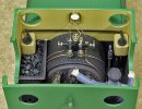
The model is quite well detailed, but one area I thought could be improved was the inside of the cab.


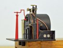
Photo No.1.jpg

The first item added was the missing reversing lever using Laurie Griffin casting No.23-005, not exactly right but the nearest I could find to the prototype. Pipe work was added from the manifold to the injector and brake cylinder on the right hand side of the firebox and injector and blower on the left side.


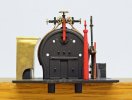
Photo No.2.jpg

A new coal bunker was added in brass on the left hand side and the backplate drilled for the new water gauges to be added after painting, and losing the red !


Photo No.3.jpg

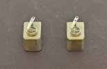
New rear sandboxes were made for fitting in the front corners of the cab at waist height. The sandboxes are just brass blocks machined to size with the corners rounded off and two holes - a 2mm dia. for the lid and a 0.7mm dia. for the operating lever. The lids were made as follows:


Photo No.4.jpg

1. A 6mm dia. brass bar was turned to 2mm dia. x 4mm long and 4.5mm dia. x 2mm long, then cut off as shown.
2. The 2mm spigot was mounted in the lathe chuck, faced off and drilled 3mm dia. as shown
3. A slot was cut across the top with a piercing saw
4. A brass strip was filed with a slight taper so the thin side just went in the slot and then it was forced in - it needs to be a very tight fit.
5. The excess brass strip was faced off and trimmed each side very gently in the lathe to the required size


Photo No.5.jpg

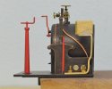
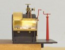
This should be the final result in the Minerva Peckett with the sandboxes fixed in the front corners of the cab and the handles connected with a rod so they can be operated from both sides of the cab, as shown on the Eric Underhill kit built W6 Peckett - its a lot easier to see how it fits when you can take the cab roof off !


Photo No.6.jpg


Photo No.7.jpg

Bunker and sandboxes temporarily bolted into place before painting - to make sure it all fitted in the cab OK. The sandbox supports and fixings won't be normally visible when its inside the cab.
 

PhilH

Western Thunderer
Photo No.8.jpg


Photo No.9.jpg


Photo No.10.jpg

Cab detail ready to go back, coal will be added to bunker top and bottom when its back in. There should of course be more pipework on top of the firebox including the pressure gauge on the cab front but the manifold is fairly delicate and I didn't want to drill any more holes in it.

Lamp Irons were added front and rear:-


Photo No.11.jpg

These were simply made from brass strip and wire:-
Photo No.12.jpg
1. Drill two holes in strip
2. Bend strip as shown
3. Insert wire bent in 'U' shape into holes and clamp strip at 'B' with spring clip to close joint at 'A'
4. Silver solder at 3 points shown in red
5. Cut off excess material as required for final shape


Photo No.13.jpg

I decided to replace the pipework and rodding between the tank and the footplate. The water valves were not handed and the operating lever was on the right side in both. Thus the rod connecting the valve to the cab was outside the tank support (adjacent to the cab) on the right hand side and behind the support on the left hand side. I used brass rod for the pipework instead of copper but it will be chemically blackened.


Photo No.14.jpg


Photo No.15.jpg

Injector detail on a prototype loco, actually a Class W6. The injector pipework is similar on the Class E but the rod running across the top photo, which operates the front sandboxes, is in front of the pipework and tank support on the W6 but behind the pipework and tank support on the Class E.
 

James Spooner

Western Thunderer
Hi Phil,

That all looks lovely and has been beautifully executed. One small practical point, is the reversing lever not the wrong way around? On all locos I have driven with a reversing lever, rather than a screw gear, the ratchet handle is at the front, rather than the back, of the lever. If you think about that from a practical perspective, it gives the driver a chance to hold the main handle in his/her hand and lift the ratchet with some fingers, without losing the ability to place the lever in the correct position.

Nigel
 

Osgood

Western Thunderer
Austerity reversing levers have the catch lever in front, but all views of Peckett levers I can find show them just as Phil’s build, perhaps all Pecketts were like that.

I recall operating a big Peckett, and in fact with the catch handle nearest driver it is easier - as you hit the reversing lever handle hard with the palm of your hand it snatches the catch lever against the handle and your fingers simply grip the handle.
So as soon as you have hold of the handle it is free to move (yes I was too hesitant once and the lever shot forward out of my hand :oops:).

With a lever having the catch lever in front you need to have strong fingers as there is a cyclical load on the reversing lever of a moving loco depending on position of valve gear which often strongly resists release of the catch pawl..
On a well run in engine the reversing lever is jumping around like a crazy thing so lunging at it works well!

Edit: It's slowly coming back: I remember having a misplaced conviction that one could get away with using just one hand - more often than not the second hand had to be brought swiftly into play as the counterweight challenged your intentions! If setting out to use two hands at least you could push or pull the lever to unload the catch before notching up or down.
 
Last edited:
Top