PhilH
Western Thunderer
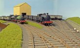
There has been little progress on this layout since the last post 2½ years ago. Work on the Austerities was suspended due to eyesight problems (cataracts) and the delay in getting these remedied due to Covid. In the meantime attention turned elsewhere to things which didn't require perfect vision and with sight improved these still tend to keep me fully occupied. At the moment I'm lost in the wilds of Colorado (that's modelwise not literally !) rather than the South Lancashire Coalfield, but its all good fun, isn't it......? 
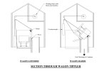
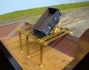
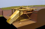
In earlier posts links were given and reference made to details of the layout originally posted on RMweb. However since the photos on there are lost (possibly never to return ?) the information given there is now probably of little use. I therefore thought it might be worth repeating some of the information here, particularly the wagon loading and unloading arrangements shown in operation in Post #20.
Starting with the loading arrangements at the colliery.
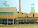
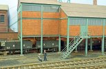
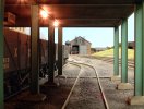
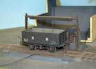
The normal method of working is as follows. Empties arrive on Track A, the engine runs round via Track B and then runs to the weighbridge/shed area ready for the next full train. If Track A is occupied the arriving empties use Track B and the loco draws forward into the siding to wait until the colliery shunter clears either Track A or Track B. The colliery shunter works the empties (left on plan) side of the screens collecting three wagons (the limit in the headshunt) at a time from the arrival tracks and propelling the wagons under the screens for loading.
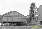
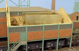
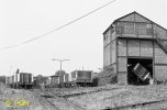
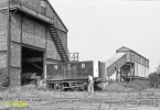
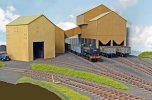
The screens are based loosely on the prototype screens at Ravenhead Colliery, St.Helens, which were somewhat larger and provided loading on 5 tracks. They were photographed after closure of the colliery with dismantling in progress.
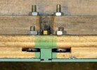
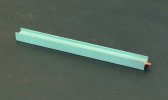
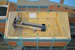
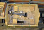
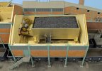
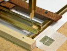
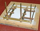
In anticipation of some form of mechanical loading the screen house construction was made fairly heavy and comprises a box of ¼" plywood supported on columns milled from square mild steel bar. Only the visible portions of the columns were fully machined to the 'H' profile, elsewhere they were just provided with a slot for the Plastikard cladding. The outside columns were silver soldered to steel plates which were bolted to the plywood walls, the bottom of the columns being machined with spigots to locate in the 'concrete' bases.
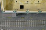
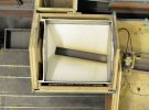
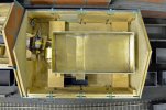
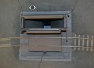
The spaces between the columns were filled with plywood panels and then faced with Plastikard brickwork, glazing and strip. I don't know whether the glazing would have been clear or opaque in the prototype but it would have been coated in coal dust on the inside so the plastic glazing was backed with grey paper. The square hole is for the future provision of loading wagons on the front track.
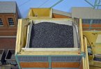
Interior columns are located in rectangular holes in the plywood floor at the top and by spigots into the bases at the bottom. Normally they would carry a layer of coal dust but that's been brushed off for the photo.
The higher rear section of the model screen building covers only two tracks for the simple reason I thought it would look more interesting. In retrospect it would probably have been more prototypical if it had been the full width of the building like the screens at Ravenhead. This higher section in the prototype would incorporate the tippler floor where the mine tubs were emptied.
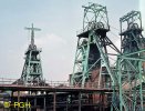
Colliery steelwork in Lancashire seems to have been predominantly light green, as shown here on the Bickershaw Colliery headframes, or light blue. The former colour was chosen for the model as otherwise the headframes would have been indistinguishable from the sky on the backscene.


