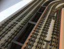
Monks Ferry: a layout for the Grandchildren.

WM183

Western Thunderer
DCC makes engines run better.

No, seriously.

DCC works on a constant 12v track power. This overcomes any track-to wheel-to pickup resistance better, and enables much smoother and more consistent performance. The older the loco, generally the more noticeable the difference. I've installed DCC in a few dozen old brass imports of American models - and had to remotor many in the process - and in every case, even remotoring, the locos ran smoother (and in particular slow speed running was improved) on DCC than on regular DC.

However, some of the new DC controllers are, in Orwellian terms, "Doubleplus good" and I've never been able to do a direct comparison with one, like some of the newer Gaugemasters, etc. For a small layout with one loco operating, like a terminus or cameo layout? DC with a good quality controller is no doubt fine. I will probably build my little Dockside layout with DC control and pokey-finger points. DCC *definitely* simplifies wiring and operation on a more complicated layout, like the one you're planning.

My 2 eurocents!

Amanda
 

jonte

Western Thunderer
DCC makes engines run better.

No, seriously.

DCC works on a constant 12v track power. This overcomes any track-to wheel-to pickup resistance better, and enables much smoother and more consistent performance. The older the loco, generally the more noticeable the difference. I've installed DCC in a few dozen old brass imports of American models - and had to remotor many in the process - and in every case, even remotoring, the locos ran smoother (and in particular slow speed running was improved) on DCC than on regular DC.

However, some of the new DC controllers are, in Orwellian terms, "Doubleplus good" and I've never been able to do a direct comparison with one, like some of the newer Gaugemasters, etc. For a small layout with one loco operating, like a terminus or cameo layout? DC with a good quality controller is no doubt fine. I will probably build my little Dockside layout with DC control and pokey-finger points. DCC *definitely* simplifies wiring and operation on a more complicated layout, like the one you're planning.

My 2 eurocents!

Amanda

Can’t disagree with any of that Amanda, so thank you :thumbs:

My pontification is fuelled in the main by lethargy :( Having to hard wire several locos - and hoping it all fits in - has seen me just reaching for the TV remote;)

Another factor is cost: while it’ll take a good couple of years to reach a level of some satisfaction with the build, like all hobbies, the majority of the outlay will be required upfront, and I’m trying my utmost to keep my good lady onside (for now :)), bearing in mind the builders and their materials are looming large in the not too distant…… Umpteen harnesses and chips will be a draw on more pressing, fundamental (layout) budgetary requirements like wood - I recently partitioned my garage and couldn’t believe the increases in prices for wood and associated materials. The pandemic really has reset the clock economically, despite any conflicting views in respect of Brexit:eek: I digress:confused:

Speaking of remotoring: the two Schools I have are the old Ringfield tender drive types, which are ideal for this not too serious venture, however, I’ve been lured to the task by a kit now available based on a CD motor replacement which really does enhance as you suggest, Amanda; but then they require chips :eek:

I’m beginning to repeat myself.

So you see, a mixture of laziness and spiralling costs are fuelling my decision at present.

However, as mentioned earlier, I am extremely indecisive, so watch this space ;)

Many thanks for your advice and interest.

Jon
 

Yorkshire Dave

Western Thunderer
DCC makes engines run better.

No, seriously.

DCC works on a constant 12v track power. This overcomes any track-to wheel-to pickup resistance better, and enables much smoother and more consistent performance. The older the loco, generally the more noticeable the difference. I've installed DCC in a few dozen old brass imports of American models - and had to remotor many in the process - and in every case, even remotoring, the locos ran smoother (and in particular slow speed running was improved) on DCC than on regular DC.

Yes, DCC improves loco control only if the loco is/was a smooth performer under conventional 12V DC control. And of course decoder CVs can be fine tuned to suit the motor/gearbox combination for optimum performance.

However, DCC is not a cure for poor running locos under 12V DC control - which unfortunately, for some, appears to be a general misconception.

My policy is to re-motor older models with a newer more efficient motor as they draw less current and allow you the option to use smaller N gauge decoders where space is at a premium - useful if you want to install sound. I've often used N gauge decoders in HO locos and HO decoders in O scale locos.

From my experience the DCC track voltage (depending upon the sytem) is generally between 14 - 18V AC.
 

simond

Western Thunderer
‘Morning, David :)

Most of kind of you to get in touch again, David.

I realised there were issues your end, so to speak, as I know you’re a regular visitor, for which I’m extremely grateful, so no worries there, David. Thanks anyway for taking the trouble to explain, and pleased that the fibre optics are doing their job once again.

Glad to learn that you’re in agreement with Dave, not that I doubted his greater knowledge than mine for a moment, but it’s reassuring to know we’re all on the same page :thumbs::thumbs:

Your interpretation of the plan sounds interesting btw. The only addition I was going to make - and something I was considering last night - was a small (runround?) loop at the far end, perhaps for storing a loco or two-car set, just to delay their immediate return to the station, if that makes sense?

View attachment 202498

It would just require the use of two more curved points so that it leaves and rejoins the mainline on a curve, although it would add about another six inches or so to the design. The extension in itself wouldn’t prove too much of a problem, being an open-frame type design to accommodate the top tier station as this is, but would have added to the expense of the build in as much as having to buy extra wood for the baseboard top which comes in handy sheets of 8’x4’, had it been a classic flat boarded train set. The only issue in this scenario, is how would it affect the wiring of the reverse loop?

Anyway, David, many thanks for you valued interest one again.

Jon

Jon
Apologies if this has already been addressed but without the pink crossover, there is no reversing loop, it's simply an end-to-end where the ends are side-by-side.

The addition of the crossover does potentially add the complexity associated with reversing loops, but I suggest this might be easily addressed by arranging the supply to platforms 1 2 & 3 (reading from the top down) to be from the inner curve when the point is set to "parallel" and to be from the outer curve when set to "cross over" This will require insulating track joints at the crossover, and a dpdt switch that follows the blades of the inner track point.

Of course, if you have two controllers, you will need a break between them - but I think you might find that you don't need this complexity.

The blue loop is not an electrical issue at all.

atb
Simon
 

jonte

Western Thunderer
Yes, DCC improves loco control only if the loco is/was a smooth performer under conventional 12V DC control. And of course decoder CVs can be fine tuned to suit the motor/gearbox combination for optimum performance.

However, DCC is not a cure for poor running locos under 12V DC control - which unfortunately, for some, appears to be a general misconception.

My policy is to re-motor older models with a newer more efficient motor as they draw less current and allow you the option to use smaller N gauge decoders where space is at a premium - useful if you want to install sound. I've often used N gauge decoders in HO locos and HO decoders in O scale locos.

From my experience the DCC track voltage (depending upon the sytem) is generally between 14 - 18V AC.
Thanks, Dave.

Never even considered opting for N gauge chips, so to speak.

Very clever :thumbs:

Jon
 

jonte

Western Thunderer
Jon
Apologies if this has already been addressed but without the pink crossover, there is no reversing loop, it's simply an end-to-end where the ends are side-by-side.

The addition of the crossover does potentially add the complexity associated with reversing loops, but I suggest this might be easily addressed by arranging the supply to platforms 1 2 & 3 (reading from the top down) to be from the inner curve when the point is set to "parallel" and to be from the outer curve when set to "cross over" This will require insulating track joints at the crossover, and a dpdt switch that follows the blades of the inner track point.

Of course, if you have two controllers, you will need a break between them - but I think you might find that you don't need this complexity.

The blue loop is not an electrical issue at all.

atb
Simon

Okey-dokey:thumbs:

Need to assimilate this, Simon, but first need to find brain and engage it.

Many thanks,

Jon
 

WM183

Western Thunderer
Hi Dave,

I have never installed a decoder in an engine and not had an improvement in running quality. No, it won't make a silk purse into a sow's ear - hence why I mentioned often remotoring those old brass engines first - but it makes good engines better, and fair runners acceptable.

Err.... make a sow's ear into a silk purse. I think.

Amanda
 
Last edited:

jonte

Western Thunderer
Hi Dave,

I have never installed a decoder in an engine and not had an improvement in running quality. No, it won't make a silk purse into a sow's ear - hence why I mentioned often remotoring those old brass engines first - but it makes good engines better, and fair runners acceptable.

Amanda
Sounds like I need to fit a chip to myself, Amanda ;)

Jon
 

jonte

Western Thunderer
I’ve been giving some consideration to what form the baseboard will take.

‘Open Top’ seems the most appropriate form to take, especially with the elevated station section and gradients, but I wanted to look at this fundamental aspect of the build with fresh eyes, so what else is out there?

The online services offering MFI style flat pack offerings looked attractive, but it would appear that bespoke jobs are POAs; so that’s the end of that line of enquiry.

The arrangement of pre shaped plywood formers used these days in the interests of weight, especially for removable baseboards, is appealing. What’s prevented me in the past from plumping for this idea is approaching the woodyards with a list of required dimensions for cutting. The problem here, is that there’s always something I’ve overlooked, which only becomes apparent once you start to fix the parts together. Imagine my excitement therefore during the summer when I discovered that one modeller was cutting sections of ply to size at home using something called a drop saw, which you can get from the likes of Argos for a reasonable sum. That said, on close up, despite using a length of planed timber as a guide, it didn’t bear close scrutiny; not a problem I suppose with a single level board, but things here a little more complex, especially when the strictest level of accuracy with gradients is essential to ensure that they don’t become insurmountable.

Thus it was back to the old planed timber frame with open top, which will be dressed with MDF side skirts, to hide the skeleton beneath. To that end, I’ve been doodling on the notepad on knee again, to assist with working out the amount of material required, together with the (spiralling) cost:

IMG_2092.jpeg

Apologies: the underboard runners are of 2”x1” planed timber (the one’s omitted), and will run longitudinally beneath the three by one mainframe to save cutting (shown in shadow to indicate that they will be inboard of the outside (longitudinal) frame).

As I say, this will make it easier to adjust gradient heights as I go - supports of more upright three by one - especially as the ‘up’ and ‘down’ gradients ‘to’ and ‘from’ the station will be on a split level.

I’ve also had to work out how to arrange the framing for the top tier station to accommodate the pillar supports, such that they will be sufficiently supported: not too high in relation to platforms and that any framing to support them isn’t too thick, as this would aggravate the percentage amount of gradient(s) required - the train has to lose/ gain the height from rail height to datum level of this top tier board, prior to allowing at least two and a half inches below for the train to pass underneath with adequate clearance.

Gradients and bent points: As I’ve said before: what a pain in the Arsenal.

jonte
 

40057

Western Thunderer
I’ve been giving some consideration to what form the baseboard will take.

‘Open Top’ seems the most appropriate form to take, especially with the elevated station section and gradients, but I wanted to look at this fundamental aspect of the build with fresh eyes, so what else is out there?

The online services offering MFI style flat pack offerings looked attractive, but it would appear that bespoke jobs are POAs; so that’s the end of that line of enquiry.

The arrangement of pre shaped plywood formers used these days in the interests of weight, especially for removable baseboards, is appealing. What’s prevented me in the past from plumping for this idea is approaching the woodyards with a list of required dimensions for cutting. The problem here, is that there’s always something I’ve overlooked, which only becomes apparent once you start to fix the parts together. Imagine my excitement therefore during the summer when I discovered that one modeller was cutting sections of ply to size at home using something called a drop saw, which you can get from the likes of Argos for a reasonable sum. That said, on close up, despite using a length of planed timber as a guide, it didn’t bear close scrutiny; not a problem I suppose with a single level board, but things here a little more complex, especially when the strictest level of accuracy with gradients is essential to ensure that they don’t become insurmountable.

Thus it was back to the old planed timber frame with open top, which will be dressed with MDF side skirts, to hide the skeleton beneath. To that end, I’ve been doodling on the notepad on knee again, to assist with working out the amount of material required, together with the (spiralling) cost:

View attachment 202669

Apologies: the underboard runners are of 2”x1” planed timber (the one’s omitted), and will run longitudinally beneath the three by one mainframe to save cutting (shown in shadow to indicate that they will be inboard of the outside (longitudinal) frame).

As I say, this will make it easier to adjust gradient heights as I go - supports of more upright three by one - especially as the ‘up’ and ‘down’ gradients ‘to’ and ‘from’ the station will be on a split level.

I’ve also had to work out how to arrange the framing for the top tier station to accommodate the pillar supports, such that they will be sufficiently supported: not too high in relation to platforms and that any framing to support them isn’t too thick, as this would aggravate the percentage amount of gradient(s) required - the train has to lose/ gain the height from rail height to datum level of this top tier board, prior to allowing at least two and a half inches below for the train to pass underneath with adequate clearance.

Gradients and bent points: As I’ve said before: what a pain in the Arsenal.

jonte
Hello

I have been looking at your plans and in particular the need to gain enough headroom for one track to pass under another in a reasonable distance without unreasonable gradients. I have had to solve this problem too. Tricks I used included:

In my reading of your planning, you need your train on the lower level to pass under the baseboard and its supporting woodwork. I put the baseboard strengthening on top of the baseboard (except around the perimeter) and you could too. Make your station platforms using the 2”x1” and use the station to give the structural rigidity to the baseboard. The height required under the baseboard can be reduced then to a minimum required for reaching the trains.

I cut a channel in the upper baseboard over the position of the lower track, to increase headroom. The channel was covered with 2 mm ply (in 00 card would probably do). The two parts of the baseboard (either side of the channel) were locked together by the station platform crossing over the top. The 2 mm ply plus the track on the upper level was more than strong enough to support the weight of trains on the upper level for the 3 “ width of the section where the main baseboard was missing.

The above two measures will reduce the height difference required between the upper and lower tracks.

The third device I used was to keep the rising gradient to straight track. On sharp curves there is considerable additional rolling resistance due to flange contact. This plus a gradient can stall a train. I have 3’ radius curves on my line from lower to upper sections. There is no gradient on the curves. The intermediate straight sections are uniformly graded at 1 in 66. Using clockwork engines, for ascending trains, it is very noticeable that trains slow on the curves (which are level) but then accelerate again up the 1 in 66 gradient of the straight sections. So with a loco at constant power, the curve is providing greater resistance than the gradient.
 

jonte

Western Thunderer
Hello

I have been looking at your plans and in particular the need to gain enough headroom for one track to pass under another in a reasonable distance without unreasonable gradients. I have had to solve this problem too. Tricks I used included:

In my reading of your planning, you need your train on the lower level to pass under the baseboard and its supporting woodwork. I put the baseboard strengthening on top of the baseboard (except around the perimeter) and you could too. Make your station platforms using the 2”x1” and use the station to give the structural rigidity to the baseboard. The height required under the baseboard can be reduced then to a minimum required for reaching the trains.

I cut a channel in the upper baseboard over the position of the lower track, to increase headroom. The channel was covered with 2 mm ply (in 00 card would probably do). The two parts of the baseboard (either side of the channel) were locked together by the station platform crossing over the top. The 2 mm ply plus the track on the upper level was more than strong enough to support the weight of trains on the upper level for the 3 “ width of the section where the main baseboard was missing.

The above two measures will reduce the height difference required between the upper and lower tracks.

The third device I used was to keep the rising gradient to straight track. On sharp curves there is considerable additional rolling resistance due to flange contact. This plus a gradient can stall a train. I have 3’ radius curves on my line from lower to upper sections. There is no gradient on the curves. The intermediate straight sections are uniformly graded at 1 in 66. Using clockwork engines, for ascending trains, it is very noticeable that trains slow on the curves (which are level) but then accelerate again up the 1 in 66 gradient of the straight sections. So with a loco at constant power, the curve is providing greater resistance than the gradient.

Hello, my friend (apologies, I don’t know your name).

My sincerest thanks for sharing your thoughts and experiences with me. Im most grateful.

With regard to your first suggestion, I came up with a similar solution last evening and scribbled the following doodle - to get right how things lie for my own benefit as I have to see to understand:

IMG_2093.jpeg

I also have to continually do conversions from millimetres to inches, and back, to gauge matters, hence the figures.

As you can see from this attached photo:

IMG_0949.jpeg

the bases of 2”x1” to which I’ve fixed the pillars, in my scenario would be acting as supports for the baseboard (as well as being supported by the baseboard top (9mm)), pretty much as you were suggesting with the platforms in your scenario. The only concern here is the lie of the track: the pillars may indeed have to form part of the platform, which at 3/4” in height are too high for a scale height in 4mm, hence the sketch which raises the track accordingly. Again in my scenario, I have ensured that the frame below the baseboard top is as thin as I can make it without losing rigidity, and for the purpose have discovered a wood yard supplying 1”x0.5” planed timber, laid such that the half inch side is the thickness of the frame. Not the best solution perhaps in terms of strength, but the math works in respect of the gradient. Of course, one mustn’t forget that the three by one supports attached to the frame below, will also add rigidity.

Earlier thoughts included just a baseboard covering (top of say 9mm) without frame below, relying on ‘three by one’ supports regularly spaced for rigidity, or the top tier fabricated traditionally of baseboard covering on 2”x1” frame, but replaced with the 1”x0.5” planed timber placed above the tunnel entry and exit points. Perhaps I’m right in thinking the latter case similar to your second.

With regard to your third point, if you don’t mind, I’ll save this to answer Simon (@simond) as he’s also touched on this in the post following yours. Incidentally, there is a formula I believe (Physics?) that can be used to calculate how a curve on a gradient increases the force required to negotiate, despite the gradient remaining the same, and to which you refer in your post.

Many thanks once again for your kind input.

Jon
 

jonte

Western Thunderer
Or make the uphill gradient straight, and allow the downhill to have the curves. Which I think you may have done by accident or design!
Indeed, Simon.

Here’s the original as I discovered it:

IMG_1872.jpeg


As you can see, the shorter, curved route from the tunnel is the road to the station in this version. The shorter length and curves would have put paid to the venture, at least in the space I have available. By reflecting the image, the ascent is now on the straighter, longer run as suggested, which put the plan back on the table.

Additionally, I will be ensuring that the slope will not start/end until a distance of approximately 6” or so out from the curved crossover. Adding a slope to a bent point is just asking for trouble in my book ;)

Cheers, Simon.

Jon
 

40057

Western Thunderer
Hello, my friend (apologies, I don’t know your name).

My sincerest thanks for sharing your thoughts and experiences with me. Im most grateful.

With regard to your first suggestion, I came up with a similar solution last evening and scribbled the following doodle - to get right how things lie for my own benefit as I have to see to understand:

View attachment 202679

I also have to continually do conversions from millimetres to inches, and back, to gauge matters, hence the figures.

As you can see from this attached photo:

View attachment 202680

the bases of 2”x1” to which I’ve fixed the pillars, in my scenario would be acting as supports for the baseboard (as well as being supported by the baseboard top (9mm)), pretty much as you were suggesting with the platforms in your scenario. The only concern here is the lie of the track: the pillars may indeed have to form part of the platform, which at 3/4” in height are too high for a scale height in 4mm, hence the sketch which raises the track accordingly. Again in my scenario, I have ensured that the frame below the baseboard top is as thin as I can make it without losing rigidity, and for the purpose have discovered a wood yard supplying 1”x0.5” planed timber, laid such that the half inch side is the thickness of the frame. Not the best solution perhaps in terms of strength, but the math works in respect of the gradient. Of course, one mustn’t forget that the three by one supports attached to the frame below, will also add rigidity.

Earlier thoughts included just a baseboard covering (top of say 9mm) without frame below, relying on ‘three by one’ supports regularly spaced for rigidity, or the top tier fabricated traditionally of baseboard covering on 2”x1” frame, but replaced with the 1”x0.5” planed timber placed above the tunnel entry and exit points. Perhaps I’m right in thinking the latter case similar to your second.

With regard to your third point, if you don’t mind, I’ll save this to answer Simon (@simond) as he’s also touched on this in the post following yours. Incidentally, there is a formula I believe (Physics?) that can be used to calculate how a curve on a gradient increases the force required to negotiate, despite the gradient remaining the same, and to which you refer in your post.

Many thanks once again for your kind input.

Jon
Hello again

For completeness, the other cunning plan I have used on Rivermead Central to lengthen the gradient, so make it less steep, is to intersperse the graded line between the upper level tracks (so not directly underneath them). I’m not sure your layout will allow anything similar — though perhaps you could use the main station building or approach road in the same fashion. This photo shows what I mean:

7C8DF9C9-A6FE-47FC-A88A-777DDE87A344.jpeg

Work still in progress, but you can see the track from the lower level under the station platform. This has allowed me to spread the gradient over almost the whole length of the line between the two levels (except for the curves, as described previously). By the far end of the platform in the photo above, the upper parts of trains on the line under the platform are just above the ‘ground level’ of the high level base board — but invisible inside the platform structure. Beyond that, the graded line will be under the road leading to the station and after that inside the buildings against the wall.
 

Attachments

  • 7A1D8D02-8312-4FBB-9338-6AF97E1E232D.jpeg
    7A1D8D02-8312-4FBB-9338-6AF97E1E232D.jpeg
    225.5 KB · Views: 0

jonte

Western Thunderer
Hello again

For completeness, the other cunning plan I have used on Rivermead Central to lengthen the gradient, so make it less steep, is to intersperse the graded line between the upper level tracks (so not directly underneath them). I’m not sure your layout will allow anything similar — though perhaps you could use the main station building or approach road in the same fashion. This photo shows what I mean:

View attachment 202689

Work still in progress, but you can see the track from the lower level under the station platform. This has allowed me to spread the gradient over almost the whole length of the line between the two levels (except for the curves, as described previously). By the far end of the platform in the photo above, the upper parts of trains on the line under the platform are just above the ‘ground level’ of the high level base board — but invisible inside the platform structure. Beyond that, the graded line will be under the road leading to the station and after that inside the buildings against the wall.

Hi 40057

Clever stuff; food for thought indeed.

Thanks for posting the photo; it’s all very apparent for me now.

Best,

Jon
 

jonte

Western Thunderer
This afternoon I took delivery of a selection of parts from LCut Creative:

IMG_2097.jpeg

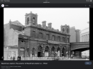
which offers laser cut parts for scratch building at very reasonable prices, that I’m hoping to cobble into something vaguely resembling Blackfriars:


Together with some bits of styrene and strip already in my possession I reckon it should look okay, although I’ve promised not to get hung up on detail, so this will only be a nod to the real thing. But still, I’m looking forward to the challenge.

Btw, the balustrade is from Model Railway Scenes, whom I’ve always found a very friendly proprietor with which to conduct business.
Cheers for now.

jonte
 

Attachments

  • IMG_2042.png
    IMG_2042.png
    1.1 MB · Views: 0

Pencarrow

Western Thunderer
This afternoon I took delivery of a selection of parts from LCut Creative:

View attachment 202836

which offers laser cut parts for scratch building at very reasonable prices, that I’m hoping to cobble into something vaguely resembling Blackfriars:


Together with some bits of styrene and strip already in my possession I reckon it should look okay, although I’ve promised not to get hung up on detail, so this will only be a nod to the real thing. But still, I’m looking forward to the challenge.

Btw, the balustrade is from Model Railway Scenes, whom I’ve always found a very friendly proprietor with which to conduct business.
Cheers for now.

jonte

Will be interested in your views on the LCut parts. I had a kit off them and found the material was more like cardboard than MDF. In the end the whole lot was binned and I made a replacement from plasticard, which was what I was going to do in the first place.
 

jonte

Western Thunderer
Will be interested in your views on the LCut parts. I had a kit off them and found the material was more like cardboard than MDF. In the end the whole lot was binned and I made a replacement from plasticard, which was what I was going to do in the first place.

Certainly; however, as I’ve never really had full faith in any MDF product - the baseboard for instance will be good ol’ ply - I intend to use them merely as fascias glued to a plasticard shell, so not sure whether any feedback would be of interest.

Jon
 

40057

Western Thunderer
Certainly; however, as I’ve never really had full faith in any MDF product - the baseboard for instance will be good ol’ ply - I intend to use them merely as fascias glued to a plasticard shell, so not sure whether any feedback would be of interest.

Jon
I took the view that the LCUT Creative parts I bought were nowhere near strong enough to form the structural elements of a 7 mm scale building. I used them as tiles to provide the cosmetic elements, glued and nailed (using panel pins) to a plywood carcass.
 
Top