2mm Modbury

Joe's Garage

Western Thunderer
I am also always amazed at the fact that this is 2mm Ian.
Even in 2 mm West Bay is in fact quite long but it too would make a lovely model.
I think you are cutting yourself short Grahame as your models are a credit to N gauge modelling.
I do like the bucket!
Julian
 

Phil O

Western Thunderer
I would have liked to have visited, but it's a difficult drive from here, and being an ex Devonport employee, I have to maintain standards!!

The emojis seem to be disabled!
 

James Spooner

Western Thunderer
Well, I wasn‘t disappointed. Although a 4mm scale modeller myself, Modbury and Drws y Nant were two stunning examples of what can be achieved in 2mm finescale these days. Both featured exquisite modelling, worked well and showed the railway as a part of a wider scenic panorama. Thank you for bringing Modbury to Portsmouth Ian.

Nigel
 

Ian Smith

Western Thunderer
Thoroughly enjoyed the Portsmouth exhibition!! With just Steve and myself operating for the day, I don't think either of us managed to get a good look at the other exhibits. However, the short time I spent away from Modbury proved that the show was an excellent one with a variety of good quality layouts/scales on offer for the public.

Unfortunately, within the first few minutes of running it was noticed that my Dean Goods had an intermittent short, so we had to deploy John Russell's somewhat out of period Collett Goods for the day, but it is such an excellent and reliable runner that we'd have run it anyway!!

I didn't manage to take many photos of Modbury (and unfortunately none at all of Nigel Ashton's wonderful Drwys-y-Nant), but here are the few I managed :

1.JPG
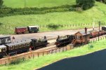
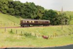
An overall view of the scenic section before the public were allowed in. Steam Railmotor just departing towards Newton Abbot. Once again, the SRM attracted a lot of interest and favourable comment.

2.JPG
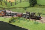
517 tank in charge of a short cattle train departing Modbury.

4.JPG
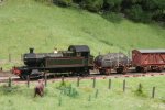
Prairie (later 45xx) draws a short Plymouth bound pick up goods over the embankment into the station.

5.JPG
A closer view of Prairie and leading wagons of Down Goods train.

Finally, fellow 2mm Association member and friend, Richard Brummitt, provided me with a surprise gift ...

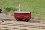
3.JPGA rather beautiful "Beetle" - a diagram W4 Prize Cattle Wagon. Richard said that he took my artwork for the W1/W5 cattle wagon and amended it. I think that is a gross understatement as the only bits recognisable from my original work are the ends and the drop flap side door!! He has 3D printed the body, and "cobbled together" the running gear from various bits of etch. The result is simply stunning and to say that I am thrilled is an understatement - Thank you Richard!! Unfortunately, because Richard uses 3 link couplings (!!!!) on his stock I wasn't able to run it on the day as it will need a set of DG's fitting.

Thank you for looking.
Ian
 

Ian Smith

Western Thunderer
In order to try to rekindle a bit of modelling mojo, today I have been playing trains having a running session on Modbury. Whilst running a few trains, I also took the opportunity to video a few of the movements. After an hour or two of editing, the result has been uploaded to YouTube :
Thanks for looking.
Ian
 

Joe's Garage

Western Thunderer
Thank you Ian for posting this video, I am selfishly glad that "finding your mojo" has taking you to producing this film for those of us who were unable to get to exhibitions to see Modbury in the flesh. The steam railmotor, as the whole layout defies the fact that this is 2mm FS!!
Unfortunately I watched this on my phone and cannot wait till I'm back home and watching it on the "big screen" !!
I do like it when you "play trains"...then post the video.
All the best
Julian
 

Ian Smith

Western Thunderer
Having been in the modelling doldrums for several months where virtually no railway modelling has occurred in Modbury Towers, over the last three or four weeks mojo has finally returned!!

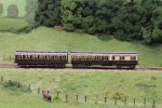
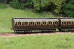
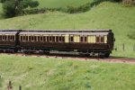
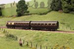
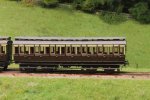
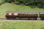
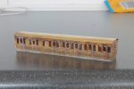
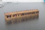
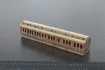
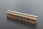
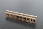
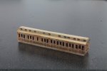
With Modbury due to attend the Loughborough exhibition in August, I have finally managed to complete the first two bogie coaches for Modbury. They are a D37 Van Third and a C4 All Third, sides and ends coming from Worsley Works with the bogies being my own etches (although the functional carcass of the 10'0" ones under the D37 were provided by Richard Brummitt with the cosmetic bits coming from my own 8'6" bogies.

The coaches in question were last seen several months ago and an aborted attempt to paint the C4 led them both to be consigned to their respective bags and put aside. Following a bit of mojo return, the D37 was finally structurally completed a couple of weeks ago, and since then the pair have progressed through the Smith paint shop.

Here are a few snaps of the pair on Modbury's embankment :
1.JPG

2.JPG

3.JPG


4.JPG


5.JPG

6.JPG
On Saturday, I took the pair along to the 2mm Expo at Derby and entered them in the modelling competitions, and am proud to say that they were awarded the "Chairman's Trophy"!! Thank you Chairman Alisdair!

With the successful completion of that pair, mojo is now fully restored, so I have now made a start on the next one in the rake - another from the Worsley Works stable, a 1st/2nd Composite (sold as an E14 but actually is an E17).

Description of that build will have to commence in a new post as I seem to have reached the picture limit in this one!
Thanks for looking,
Ian
 

adrian

Flying Squad
On Saturday, I took the pair along to the 2mm Expo at Derby and entered them in the modelling competitions, and am proud to say that they were awarded the "Chairman's Trophy"!! Thank you Chairman Alisdair!
Congratulations - they do look rather good.
 

Ian Smith

Western Thunderer
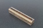
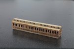
As mentioned in my previous post, I have made a start on another clerestory bogie coach to accompany the All Third and Van Third recently completed. This one too comes from the Worsley Works stable and is marketed as a diagram E14 - a 1st/2nd Lavatory Composite. A look through Jim Russell's "A Pictorial Record of Great Western Caoches (Part 1)" provides a diagram for the E14, but unfortunately when referring to Richard Spratt's website Great Western Railway Dean Era Coaches - Non Corridor Clerestory Bogie Coaches, the E14 is shown as having 12" deep eaves panels (and no lavatory facilities). Further down the page though is the diagram E17 which is a match for the sides produced by Worsley Works.

Therefore using the sides and ends of the kit I intend to build it up as an E17. The rest of this post will be a set on annotated photos of the build so far (although I omitted to take any of the early part of the build!) :
1.JPG
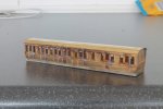
The main carcass of the coach assembled. While the sides were still on the fret, I soldered all of the door vents in place. Once the turnunders (tumblehomes) were formed, the sides and ends were soldered together using the fold up internal bracing pieces to strengthen the corners (at the bottom), these bracing pieces also include a hole to attach underframe to body, so a 12BA nut was soldered in place on the upper side of these holes.
A rudimentary underframe is included in the kit, comprising a flat floor under which a bent up solebar and upper step is soldered. A pair of headstocks complete the bits that are included in the scratch aid kit. One thing I did have to do was to drill new holes for the bogie pivots some 1mm inboard of the etched holes. More 12BA nuts were soldered above these new holes in readiness for attaching the bogies later.
A roof was cut from some 0.005" brass sheet and rolled to the profile of the ends - I tend to do this on an old mouse mat using steel bars to get a general shape, then burnish the roof to final shape around suitable bar stock with a thick wooden lollipop stick (from a "Magnum"). Once formed it was soldered in place which combined with the embryonic underframe gives the body a reasonable amount of strength.
Finally, as is my wont, I solder all of the G hand rails and door handles in place on the sides. I much prefer to solder these things in place to ensure that they are really secure - during the build the model will be scrubbed after each build session so any bits that aren't secure will come away at some point!!


2.JPG
The other side showing the step end. The steps are part of the internal end brace and have to be folded out and project through slots in the end proper.

3.JPG
The next stage was to add the clerestory on top of the main roof - annoyingly, the clerestory ends were not included on the etch (an oversight I expect), so these had to be fabricated first from some spare etch, luckily the E17 had an arced roof to the clerestory by a three-arc profile for the main roof. A lightly scribed line down the centreline of the roof aided getting the ends centred, then the sides were tack soldered in place then the joints made good once I was happy.

4.JPG
Once the clerestory sides and ends were secure, I attacked the gap down the middle with a slitting disk and files so that I would be able to get an iron in to solder the roof on the clerestory and also so that I can glaze it once fully painted. Those of you paying attention might notice that I have put this side of the clerestory on upside down and the wrong way round - the blank portion should be above the luggage compartment doors. I didn't actually notice this until I had fitted the clerestory roof, so had to remove the roof and this side then reassemble it all the correct way once I'd straightened out the somewhat mangled clerestory side!! Oh how I laughed!!!

5.JPG
The completed clerestory roof.

6.JPGAnd the other side having had my earlier mistake corrected!

7.JPG
At last night's Midland Area Group meeting, I managed to add the rain strips to both the main and clerestory rooves. These are simply made using strands from multi-core flex (each strand being 0.15mm diameter). A strand is straightened by rolling between my cutting mat and a steel ruler. Then positioned on the roof and initially tack soldered in place and once satisfied flood with flux and the bond along the length made good. A sharp knife trims off the excess hanging over the ends of the coach before the next strip is applied. A thorough stiff rubbing with a fibreglass stick removes all of the excess solder on the roof.

8.JPG
Todays task has been to turn and fit the gas lamp tops on the clerestory roof for the 1st and 2nd compartments and on main roof for the lavatory compartments.

The next task will be to fit the gas piping (and lamp feeds) along the roof, then fabricate and fit the handrails on the step end, and finally fabricate the brake tell tails to the non-step end. Then I can move on to the underframe. The Dean 6'4" bogies have already been made up ready - these are from my own artwork and custom etch - although I have yet to fit the volute springs to them (although they too have been turned up in readiness).

Thanks for looking
Ian
 

Attachments

  • 5.JPG
    5.JPG
    145.6 KB · Views: 1

Ian Smith

Western Thunderer
As a bit of a change from making and painting coaches, I've begun adding a little more life (or rather wildlife) to Modbury.

The catalyst for actually getting on and doing something (as I've intended to do this for quite some time) is an invite to the Manchester exhibition in December. In filling out the documentation requesting all of the normal things like size of layout, number of sockets required, etc, at the end was a little section asking for a couple of questions for children to answer as a type of "treasure hunt" (something along the lines of “How many dogs in the main street of Dewsbury Midland?”).

Now, I must admit that I've never considered a target audience of children for Modbury (although we do have a series of little cameos on St. Ruth for children to find - my effort was a picnicking family whose child has got her kite stuck in one of the trees). However, although there are some "cameos" on Modbury they are there more to breathe life into the scene rather than the "can you spot ..." kinds of things.

Examples of the "cameos" already in existence :
9.JPG
Couple awaiting their train for a day out in Torquay

10.JPG
Sisters patiently waiting for their train for their "new hat" shopping trip to Exeter

8.JPG
Coal merchant John Clarke discussing business with a customer

So back to the wildlife!!! I intend to model some rabbits at some point but decided some bird life would be a nice touch to start with. Now, clearly in 2mm scale something like a wren or even a blackbird would be a bit pointless, so I've elected to model something a little larger - some pheasant. According to my ancient "Observers Book of British Birds" :
1.JPG

The pheasant would be between 4 and 6mm long in 2mm scale, so actually reasonably visible. These little chaps (and chapess) were simply formed with a length of 0.45mm brass wire for head body and tail (left over long at each end!!), with a couple of twists of 0.3mm wire to bulk out the body and provide a leg to mount in the scenery. Once soldered together, further 70 degree solder was used to build up a bit more mass before final bending to shape and thinning with a small needle file.

Unfortunately I forgot to take any construction photos, but once primed and painted the results were quite pleasing (although difficult to photo) :
2.JPG
3.JPG

It was then a simple matter of deciding where to put them - in the end I elected to put them where they would be most visible (at the front of the layout around the hedge that disguises the board joint) :
4.JPG
The lone male looking for something tasty in the grass

5.JPG
And on the other side of the hedge the "old married couple". I have since touched up the male as I had inadvertently damaged his plumage with my tweezers as I forced his leg into the ground.

One thing I did notice a couple of weeks ago was that one of my platform trolleys had been lost in transit at one of the recent exhibitions. The missing trolley was part of another small cameo on the down platform consisting of a couple who were taking some of their produce from their market garden to sell in Plymouth. The original trolley had a couple of crates of greenery on it, but having to create a replacement has led to something a little more adventurous!

The trolley itself is one of my own etchings which was soldered/superglued up and painted. I then made a couple of wooden boxes (I felt that wicker baskets were a little too tricky although I did try weaving some 0.1mm wire between staves a little thicker!) from 0.005" plasticard with a 0.015" bottom. An additional pair of stacked crates was also made from small squares of 0.020" plasticard, the middle layer having its sides filed away to leave small squares at each corner to represent the upstanding corners of the lower crate. Once painted, the voids in the side of the middle layer were dressed with a little green flock, as was the top. The two wooden boxes have been filled with cauliflowers and cabbages - the hearts of each being small balls of pre-coloured tissue, then outer leaves of more pre-coloured tissue being added. Once dry a few cabbages were glued in one box and cauli's in the other.

6.JPG

7.JPG

That's all for now. Thank you for looking.
Ian
 

michael mott

Western Thunderer
Wonderful work Ian, I have some commercial plastic N gauge coaches and your description of building the clearestoy one just leaves me amazed. The scenic items are lovely, the cauliflowers look good enough to eat.
Michael
 

oldravendale

Western Thunderer
The peasants pheasants peasants should be diving in front of the train. They do that all the time to me when I'm driving, especially at "Schools Out" time.

I jest, of course (well, not about kids and often their yummy mummys jumping in front of the car at Schools Out time. It must be my magnetic personality).

Lovely stuff, Ian.

Brian
 

Ian Smith

Western Thunderer
Over the last few days further remedial work has been applied to Modbury. After the Wells exhibition a couple of years ago I noticed that two of the platform oil lamps on the near Up platform had been damaged - in fact all that remained of them was the posts glued into the platform, the glazed portion and their supporting "cages" had been knocked off and lost. At the time that I noticed this damage, I extricated the two posts and put them somewhere "safe". Needless to say that those posts are still in that "safe place"!!!

When I originally turned up the posts, I made 11 all told - 5 for each platform and one for the cattle dock. Two of the originals had never actually made it to completion so the nearer Up platform lacked a couple anyway. With the missing pair I decided that I really ought to rectify the situation in readiness for Modbury's next outing (publicly at Loughborough in August, but I'm also taking Modbury to the Great Western Study Group AGM in Didcot at the end of the month.

So, first up I needed to make a couple of new posts to replace the pair that are lurking somewhere in a "safe place". This is a reasonably easy turning operation from 2mm round brass bar with gravers in the lathe - the form being a tapered column with a small collar about 0.5mm from the top, and the lower 1mm being formed into a stepped foot (along with a mounting spigot below). The whole visible turning being 12mm (6'0") tall. The "supporting cage" at the top of the post is formed from an X soldered onto the 0.5mm section above the collar, the arms of the X being carefully bent around so that the glazed section could be glued on top. Incidentally, the X is actually some 4mm scale glazing bars from some etched signal box windows.

The glazed portions (and their roofs) were formed from a piece of 3mm thick perspex sheet which was cut and milled to be 3mm square bar. The facets of the glazed portion were then milled at a 10 degree angle and polished before being cut from the bar and the roof facets filed on. A flat was filed at the roof apex and a 0.55mm hole drilled. The vent and finial at the top of the roof were formed with another little turning (again with a graver) with a 0.5mm hole drilled down it for a piece of 0.5mm wire which in turn was filed to represent the finial.

Hopefully, the photos below will illustrate :
1.JPG
The four new lamps (two original posts turned in nickel silver, the two new ones from 2mm brass rod). The left-most post shows the 4mm signal box glazing bars soldered on top, next to it is the roof vent and in front of that the perspex glazing (including the roof).

2.JPG
The four completed lamps ready for installation.

And finally, a view of the lamps in place on the layout :
3.JPG
One of the replacement lamps is hidden by the building in the is view.

Thanks you for looking.
Ian
 
Top