2mm Modbury

Ian Smith

Western Thunderer
A little more progress on the 45xx ...

Firstly, the slide bars have been fettled and fixed to the cylinders. The slide bars were fabricated from a short piece of Association plain nickel silver rail, the rail was trapped in the vice jaws and filed to reduce its height to about 0.5mm - giving me a roughly 2" piece of 0.5mm square(ish) rod for the slide bars. A couple of the cylinder ends that I had already made were double sided taped to my vertical slide (actually a sacrificial piece of Tufnol bolted to the VS), the 0.6mm centre hole in each was located and the VS moved 0.062" vertically above and below that hole to drill 0.7mm holes through which I could solder the slide bars. The ends of the cylinders also received a short 0.7mm hole (using the end caps to site the drill) to give a more secure location for the ends of the slide bars. It was then a reasonably simple operation to solder the slide bars through the end caps into the cylinders.

A quick aside - when filing the rail down to the correct height, it helps to have a micrometer or Vernier Calliper locked off at the size required and try to slide the piece between the jaws, if it doesn't quite fit file a bit more off until it does. Doing this helps to identify any high spots along the length which can be filed or sanded appropriately.

45-24.JPG
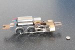
The cylinder blocks with then "end cap" and slide bars in place.

45-25.JPG
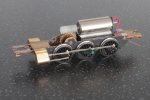
And temporarily fitted ono the chassis by their mounting pegs. The next stage will be to fabricate the motion brackets - the plan is to file these from some 0.020" NS and solder them in place on the slide bars (a mounting peg being used to locate them to the chassis side)

Yesterday was spent lining out the body (the body having received its coat of GWR green a couple of days previously) ...

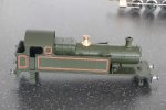
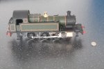
Once again I have used Fox transfers for the lining. As can be seen in the following photos I have also turned up a new Safety Valve cover.
45-26.JPG

45-27.JPG

45-28.JPG
I don't know how whether the bunker rear was lined as the only photo I could find of an early engine (in works grey) is a 3/4 frontal shot in Russell's Engines book). I have therefore assumed a rectangular panel. I think that the boiler and firebox bands should also be lined but I have elected not to do this as I think it will look a bit too "busy". I may revisit that opinion though - thoughts?

45-29.JPG
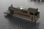
A final view of the loco with body plonked on top of the chassis (the mounting pegs on the cylinder this side are a little loose in their respective holes)

I was hoping to have completed this little engine ready for Abrail next Saturday (4th March), but I have a busy week next week so may just try to get the body finished and pop the pony trucks back on and complete the motion after the show.

Thanks for looking
Ian
 

paratom

Western Thunderer
For my next 2mm scale engine I had been considering an Armstrong Goods 0-6-0 tender engine (which I will also build) but in the end I've decided to begin work on a GWR "Buffalo" 1076 class. This engine is effectively a tank engine version of the Armstrong Goods, having the same wheelbase but slightly smaller wheels (and obviously no tender), and also has outside frames. For my chosen period (c.1906) nearly all of this class still had their saddle tanks (they were later rebuilt with pannier tanks).

Drawing on the experience of my first 2mm scale engine (my 1854 class saddle tank), I decided that this one will be fully scratch built (the predecessor being a "conversion" from a Farish 57xx - I say "conversion" because in reality there isn't a huge amount left of the Farish model!). One of the main things that bothers me about the previous model is that there is no rivet detail on the saddle tank where the plates of steel were joined together. It looks OK from normal viewing distances, but I know it's missing - I could add some using Archer's rivet transfers I suppose, but as I said in my RMweb blog when I was building the model there are other compromises so eventually I will probably give it a complete new body. That said, it did what I hoped it would do - to allow me to prove to myself that I could model in 2mm Finescale, and more importantly get a locomotive to work in the scale.

However, I've digressed. So on to the "Buffalo"...

As mentioned above, for this model I intend to put a representation of the rivets on both the saddle and the outside frames. To this end, the first thing I needed was a rivet press!! So, armed with various pieces of steel I made myself one!
View attachment 47025
This has been made so that I can locate it in the lathe chuck, and use the cross slide and top slide (locked at 90 degrees to the cross slide) to allow evenly spaced rivets to be pressed into some sheet material.
View attachment 47024

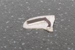
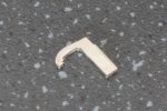
So today, I have done just that. A piece of 0.005" brass was cut roughly to size and mounted on the lathe and a good many rivets pressed in at a 0.020" separation. I'm not a rivet counter, and all I'm after really is some relief to an otherwise plain area of sheet metal. Once all of the rivets were pressed, the brass was finished to size and rolled to the profile of the saddle - I had previously fretted out a pair of formers of the correct profile for the front and rear of the saddle (one will actually be the smokebox front eventually) - and the whole lot soldered up. Below are a couple of photos complete with the requisite coin of the realm to illustrate the size.
View attachment 47023

View attachment 46866

Now I've managed to prove that my riveter works, and that I can form the saddle the next stage will be to begin work on the chassis. For this I will utilise the same method as I did for my Metro Tank, and will mill up a solid brass chassis albeit retaining the standard 2mm scale split axle methodology of construction.

Ian
Lovely work Ian, I think Jerry Clifford has met his match. How did you get the rivets so close the the edge without distorting the edge or did you cut the brass to the edge of the rivets?
 

Ian Smith

Western Thunderer
Lovely work Ian, I think Jerry Clifford has met his match. How did you get the rivets so close the the edge without distorting the edge or did you cut the brass to the edge of the rivets?
If I remember correctly, I put the rivets in place then filed the edges of the sheet back to the correct length of the saddle, then rolled it to fit the profile formers.
Ian
 

Ian Smith

Western Thunderer
More progress on the 45xx ...

Following the gentle persuasion by friends over on RMweb (and my own guilt), I have applied the lining to the boiler bands. As I suspected, the transfers did not sit particularly well on the moulded boiler bands (the main reason for my originally electing not to line the boiler bands) - the bands were slightly domed and slightly narrower than the Fox transfer lining. However, with a little persuasion and a swift waft of satin varnish after they'd had time to dry off the lining is now all in place and secure.

The original light springs I'd soldered to the chassis to allow pick up from the pony trucks had been quite badly damaged during the handing of the chassis so they have been replaced with new pieces of phosphor bronze wire - the wires at the front bear on the pony truck axle, while the rear pony truck has the wires bearing on the PCB spacer (obviously gapped, and having a short strip of plasticard glued over the gap to ensure that the wires only bear on the side of the PCB that they should do).

DG couplings have been added as has some coal in the bunker. The safety valve cover was given a coat of gloss varnish after polishing, and a couple of representative whistles turned up in the mini drill. The brass surrounds of the porthole windows have also been turned up and fixed with canopy glue.

She is now ready for this Saturday's outing to the Abingdon & District MRC's exhibition where Modbury will be on show. Hopefully in the next week or so I will get the outside motion added so that by the next exhibition (RailEx in May) she will be completed!!

Anyway, a couple of photos to show the current state of play :
45-30.JPG
I didn't realise until I uploaded the photos that the rear pony truck wasn't on the track! The photo also shows a little stray black paint on the firebox - not really visible to the naked eye - I have now removed it with a thinners moistened brush.

45-31.JPG

Thanks for looking
Ian
 

Ian Smith

Western Thunderer
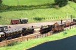
Just a few photos of the layout at AbRail a couple of weeks ago :


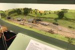
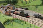
0.JPGAn elevated shot taken first thing Saturday morning just after I'd put the stock on the layout.
1.JPG
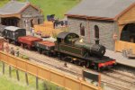
My 45xx (eventually to be numbered 2161) managed to have a reasonably successful running during the day. It was confined to pulling a short Through Goods though as when I tried to shunt some of the consist into the yard the rear pony truck derailed as the engine reversed. Since returning to base, I have rectified the problem by adjusting the pick up springs bearing on the truck and also added a small patch of lead to give it a little extra weight.


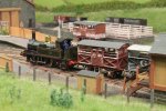
2.JPG45xx heading a short goods train. The 3 plank and 4 plank wagons have loads of bricks from the Steer Point brickworks further along the line.
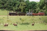
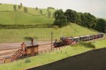
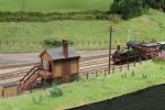
3.JPG
Dean Goods (No. 2569) heading another goods train along the embankment in the Plymouth direction.

4.JPG
Cattle train hauled by a 517 (No. 551) slows to a halt to exchange single line token at the signal box.

5.JPG
A closer view of 517 no. 551 drawing to a halt at the 'box.

6.JPG
With the tokens exchanged and the starting signal (at the far end of the platform) released, No. 551 gently accelerates the cattle train away. The stands of thistles in the adjacent field are in flower or going to seed.

Thanks for looking.
Ian
 
Last edited:

Joe's Garage

Western Thunderer
A "like" is an understatement...as I have said before this is definitely a very realistic layout. I feel I am sitting on the fence watching the trains roll by when the railways were at their zenith.
Thanks again Ian for sharing.
Julian
 

Ian Smith

Western Thunderer
Progress on the 45xx has been positively glacial over the last few months. However, I feel an update is in order as quite a bit of progress has been made in the last couple of weeks, probably because I've been spurred on by realising that Modbury's next outing to RailEx (Stoke Mandeville) is only now a few weeks away at the end of May!!!

The previous instalment of the project showed the state of play prior to Modbury's last outing at AbRail, where the body was essentially complete but the lack of outside cylinders made the loco resemble one of the few 39xx (a Dean Goods tender loco conversion to a Prairie).

As may be discerned thoughout this post, my modelling methods can be somewhat organic and evolve as things progress!!!

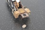
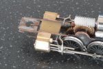
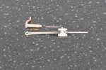
In the interests of getting as much weight into the loco as possible I decided to "carve" the cylinders from solid brass (I think a photo of this may have appeared earlier up thread). A 0.6mm hole was drilled through the blocks for the piston, and a pair of 0.5mm square (approx) slide rods were filed from a length of Association plain rail. The cylinder head covers were turned from some Nickel Silver bar and a corresponding 0.6mm hole drilled for the piston rod. A couple of 0.7mm holes were drilled at the outside edges of the covers to accommodate the ends of the slide bars (the covers were used as a jig to drill corresponding holes in the cylinder blocks). Finally, the slide bars, end covers and blocks were united with solder :
45-24.JPG
Also evident in this view are some short pegs of phosphor bronze wire inserted into the rear faces of the cylinder blocks - these are to locate the blocks onto the side of the chassis (the intention being to eventually araldite the block in position).

The next step was to create the cross heads and piston rods. Luckily, I had a couple of suitable cross head "faces" in my spares box left over from the N Brass cross head kit that I'd used on the Steam Rail Motor. However, I sill needed to fabricate the actual "slide" part of the cross head ...

Therefore, a strip of 0.75mm nickel silver about 3mm wide was carefully filed such that it had a couple of channels along each edge, that allowed it to sit within the slide bars and in profile looked like a squashed top hat :
45-32.JPG

A short piece of this was then cut off to be a little longer than the cross head, and a 0.3mm hole drilled centrally before it was attached to a bit of brass bar (the first one I super glued to the bar but for the second I elected to affix it with solder). The bit of bar (with the rear of the cross head in place) was held in a vice on my vertical slide on my lathe and a 1.5mm milling cutter deployed to remove a channel from the 0.3mm hole out beyond one end of the bar :
45-33.JPG

Once the rear of the slide was removed from the bar and cleaned up the face of the cross head was soldered on the front. A 0.45mm hole was drilled into the solid end (i.e. the end that had not been milled away), a bit of careful sawing and filing around the hole gave a reasonable impression of the cross head, so a piece of 0.45mm steel handrail wire soldered in place. A suitable piece of Association etched coupling rod was sourced, filed to a taper and a 0.35mm hole drilled for the little end. The etched face of the cross head had an absolutely huge pivot hole etched in it, so I made a couple of pivot pins from some roughly 1mm nickel silver rod/wire with files in my mini drill. The pins had a head of about 0.6mm and a shank of roughly 0.3 to 0.35mm. It was then a "simple" matter of popping the pin through the face of the cross head, through the little end and finally though the rear of the cross head and soldering the pin in place. Obviously, before the soldering was attempted, the holes in the little end and rear of the cross head had to be opened out a little to ensure that the little end pivoted freely in the cross head, and of course a couple of extra pins had to be made after the originals pinged out of the tweezers and into oblivion!! As an aside, I tend to chemically blacken bits that I don't want to solder together, and this can be seen in the following (rather blurred) photo :
45-36.JPG

The motion brackets were filed from some 0.018" nickel silver. I first made one, and once happy with the fit around the slide bars it was soldered onto a further piece of 0.018" and used as a template to form the other :
45-34.JPG

45-35.JPG
As can be seen, I left quite a hefty "handle" on the insides of the motion brackets, originally intending to cut that off as the position of the brackets is quite close to the leading drivers.

The two brackets were then separated and cleaned up an tweaked so that they fitted their respective side bars. The original intention was to just have the brackets hanging in mid air supported solely by the slide bars, but in the end I elected to make use of the "handles" that I'd formed them with (albeit thinned down considerably) to allow the brackets to be securely attached to the chassis. Of course this fixing had to be joggled to clear the leading drivers, but now engages in a slot filed into the top of the chassis frame giving a much more robust fixing (this joggle can be seen in the photo above of the cross head and connecting rod). The fixing can also be seen more clearly in the following pair of photos with the cylinders araldited in position on the chassis :
45-39.JPG
The cylinders in position, the motion on the left hand side is complete, and has had the cylinder end cap super glued in place. The end cap for the RHS is also evident and shows a piece of 0.7mm nickel silver wire soldered in place through the end cap - the the piston rod hole at the leading end of the cylinders was opened out to accommodate the stub of wire projecting at the rear of the end cap.

45-38.JPG
The completed right hand side motion. As can be seen a representation of the valve has been fitted - this is just a piece of 0.3mm NS wire with a copper wire double twist (i.e wrapped around twice) soldered in place. Also evident in these photos is the leading pony truck spring wires - these are soldered to the edge of the framing and bear on the stub axles of the pony truck.

The motion on the right hand side of the loco has the added complication (well complicated for my little brain) of the vacuum brake pump on that side. This needed a pivot from the cross head, a thin piston rod then leading back to the pump itself. With clearances being a bit tight, I decided that a strip of 0.006" nickel silver soldered to the rear face of the cross head was the way to go, and a 0.3mm hole was drilled at the top of that and an L shaped piece of 0.3mm NS wire soldered in said hole. Obviously, all of this extra paraphernalia on the top of the cross head meant that it would no longer pass through the motion bracket!! Remedial action with fine files excavated enough clearance in the motion bracket support so all was good!!

The vacuum brake pump is a simple little turning with a 0.45mm hole down its middle to accommodate the 0.3mm piston from the cross head. Looking at photos, this had a square casting at the rear end, so my little tube was soldered vertically onto a piece of 0.5mm phosphor bronze (didn't have to be PB, just happened to have a suitable bit of material the right sort of size on the workbench). Once I was happy that the tube was perpendicular to the PB, files were deployed to create the square end, and provide a fixing peg. Once again, the fixing had to be joggled to avoid wheels but the advantage was that I had a few thou available by adjusting the angles of the joggle to get the vacuum pump in the right place :
45-37.JPG

The photo below shows the RHS motion (including the vacuum brake pump) temporarily in place :
45-40.JPG

And finally, with the body plonked on top :
45-41.JPG

That concludes this particular episode, there is still quite a bit to do especially to make the vacuum brake pump look like it's actually fixed in place rather than just hanging there like it looks at the moment. And I might see what other pipework I can add around the cylinders. Although at the end of the day this (like everything else I make) is to run on a layout and not made for a showcase.

Thanks for looking.

Ian
 

Ian Smith

Western Thunderer
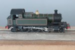
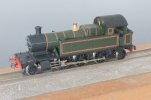
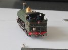
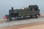
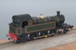
With RailEx just a few weeks away, I have finally "finished" the 45xx (although it still awaits its number plates, which are on order from Narrow Planet).

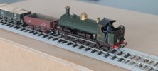
A couple of photos of her to close this element of the project that is "Modbury" ...
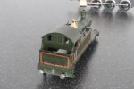
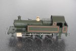
45-42.JPG

45-43.JPG

There is a little bit of touching up of the paintwork still to do (which only really becomes apparent when you take a photograph of your model!!!)

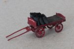
Another side project that has just been completed is a "Rulley" (cart) for my coal merchant ...

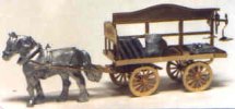
Some time ago, I picked up an N gauge Shire Scenes Coal Cart from the Dart Castings stand at an exhibition. I had never built the kit because I felt that the type of horse drawn vehicle it represented was a little to ornate for a sleepy South Devonshire town coal merchant.
SH-S22N.jpg
Internet image of the N Gauge kit

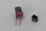
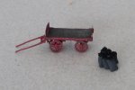
A look at the various parts included in the kit indicated that I could with a little adaption make the sort of vehicle that I felt would be in keeping for my fictional coal merchant. I built up the bed and underframe of the cart as per the manufacturers "instructions" (although I decided to employ soldered construction rather than the advised super glue). The central divider and name board along with the balance scales I discarded. However I used the "head board" to make a lower head board and a tail board (as you can see I have absolutely no idea what all of these various bits of a horse drawn dray/rulley/cart are actually called, but hopefully you'll understand what I'm talking about!!) Once soldering was complete, the model was washed and primed and finally given a coat of red before being "muckied up". I purposely built up the model as two parts - (1) the leading wheels and associated underframe carriage parts (including the shafts that the horse goes between), and (2) the rear wheels, underframe carriage and bed of the vehicle. The idea being that I could then orient the steering part to wherever I placed the model on the layout.

I was going to try to paint my coal merchants name on the head board, but before making such a rash decision I decided to have a look through my transfer stash to see if anything might be of use - I new that I had some ancient Woodhead pressfix transfers that almost certainly would have lost their sticky. Luckily, and most surprisingly, the transfers still stuck, so my merchants name was built up from some sub-1mm lettering (and a full stop) from the sheet and secured with a coat of matt varnish.

A couple of chains (of twisted fine wire) were added hanging down just in front of the rear wheels (I think they were a form of hand brake, allowing the wheels to be tethered to prevent rotation).

For a load, I made up some sacks from milliput, the tops of which were sliced off (to provided a flat face onto which I could glue some coal pieces) and once stuck together and painted dirty black, the coal pieces were affixed with gel type super glue.

Photos of this little addition to the layout :
IMG_4696.JPG

IMG_4697.JPG

IMG_4698.JPG

Thanks for looking.
Ian
 

MarkR

Western Thunderer
With RailEx just a few weeks away, I have finally "finished" the 45xx (although it still awaits its number plates, which are on order from Narrow Planet).
I hope all is well at Narrow Planet, I am still waiting for part of an order from last December, i received the nameplates, but no cabside, smoke box number plates or shedcode, unfortunately I have not received replies to emails enquiring about the missing items

Mark
 

Herb Garden

Western Thunderer
I hope all is well at Narrow Planet, I am still waiting for part of an order from last December, i received the nameplates, but no cabside, smoke box number plates or shedcode, unfortunately I have not received replies to emails enquiring about the missing items

Mark
I raised and order with light railway stores/narrow planet back in 2021 and still haven't received anything..... Must be some communication blackspot or something as they have provided a superb service every other time
 

MarkR

Western Thunderer
I completely agree, previous service has been excellent, that’s why I am a little concerned this time.
 

Ian Smith

Western Thunderer
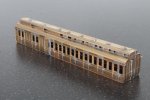
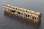
With my modelling mojo finally returned, over the last few days I have been working on a Worsley Works coach that I started several years ago. The coach is a D37 Brake Third with a clerestory roof, and I had put it to one side after erecting the sides and ends because I was not happy with the guards lookouts (some refer to them as "duckets").

Over the last week or two, the lookouts were removed, and re-attached so they no longer look quite as wonky as they did. The main roof is cut from 0.005" brass sheet, and the area where the clerestory would go was cut away so that I could get the iron in when attaching the clerestory roof. Once the clerestory sides and ends were attached to the main roof, another piece of 0.005" brass was cut and rolled for the clerestory roof - this was the very devil to form as being narrow trying to roll the 3-arc profile required tasked the patience somewhat!! The rain strips are simple lengths of straightened copper wire soldered in place - tacked in the centre, then occasionally around the arc, once happy the solder is flowed so that the whole rain strip is secure, and the excess trimmed from the ends of the coach.

As is my wont, I sweated the G commode handles in place and fitted the door handles by soldering from the inside - both types of handles being provided on a little N Brass etch. Once all of the painting is complete, these handles will be scraped back to bare brass before the protective coat of varnish is applied. I prefer to have these types of thing firmly soldered in place, and as the model is built, it gets several good scrubs with cream cleaner so any poorly affixed ones come adrift long before the model enters the paint shop (luckily, this rarely happens anyway).

The lamp tops are some simple turnings from 1.5mm nickel silver rod, and once secured in the holes drilled to accommodate them the pipe feed was soldered in place along the roof and down the end from 0.2mm nickel silver wire from Albion Models. Finally, thin copper wire is soldered from the lamp top to this main feed and the excess cut away. The brake tell-tale on the end of the coach is also formed from the Albion Models straight 0.2mm wire, tiny loops being formed in the ends before being filled with solder.

Below are a couple of photos of the coach body, it is now ready to enter the paint shop (hopefully the primer coat will not reveal too much that needs attention!!) :
1.JPG

2.JPG

Thanks for looking
Ian
 

Ian Smith

Western Thunderer
A little reminder that Modbury will be at RailEx, Stoke Mandeville, Aylesbury this weekend (27th -28th May 2023) - Railex Model Railway Exhibition. There is a good presence of 2mm finescale layouts on show (Freshwater, Kyle of Lochalsh, Bath Sheds & Modbury), along with various other delights in a variety of scales.

9 copy.jpg
An Up local passenger train of 6 wheeled coaches headed by Metro tank 615 departs from Modbury, while a pick up goods hauled by a Dean Goods pauses at the signal box awaiting the single line token before it can proceed towards Plymouth.

Hope that some of you will be able to come along to RailEx and say hello.

Thanks for looking.
Ian
 

Ian Smith

Western Thunderer
Been a bit side-tracked recently (see later in post), but yesterday I decided to tackle something that I've been putting off for ages - loco buckets.

Inspired by Trevor Pott's article in the latest MRJ (No. 297) on his Aberdare loco (and the small details he's made to accompany it), I decided that I really couldn't put off adding some of these details to my own locos. The accompanying drawing of a bucket shows in the article shows them to be about 1'0" diameter at the rim, and about 1'0" high overall.

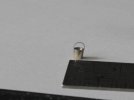
To make mine, a length of 2mm diameter nickel silver was chucked up and a taper turned with the cross slide set to some 4 degrees. A 1mm milling cutter was used to bore into the embryonic bucket, then a graver was poked into the hole to widen it out to give a thin lip at the rim. A piercing saw was used to part the bucket from the rest of the rod, and the bottom of the bucket then addressed with a fine file to bring the height down to about 2mm. The handles were formed from some 41swg (0.112mm) phosphor bronze wire which was tinned before forming into a long U shape around round-nosed pliers. The tails of the U were cut off appropriately, and the tails then soldered to the outside of the rim of the bucket - to assist in this tricky operation, the bucket was sunk into a hole in a piece of tufnol (not sure of the exact size of the hole as it was one of many that that particular piece of tufnol has in it, but suffice it to say that the bucket protruded from the hole by about 0.5mm and was held firmly).

IMG_4716.JPG
One of the pair of buckets made so far. The enormous rule gives an indication of the true size of the bucket!!

IMG_4717.JPG
The other bucket made has already been hung on the tool hook on the rear of my "Buffalo" saddle tank.

IMG_4718.JPG
Another view of the "Buffalo" with its full complement of bits and bobs hanging on the tool hooks on the bunker.

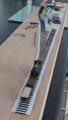
Now to the real reason not much else has been done!! As can be seen in the photo above, the tank engine is not sitting on a length of baulk road track!!! I have started to make myself a little "test plank" - quite some time ago I built the board from a piece of 4'0" x 6" x 4mm plywood using some strips of MDF for the frame. And there it had sat with me debating whether I actually needed a test track given that Modbury is permanently set up in my living room. However, a couple of weeks ago I noticed the board leaning up in the corner of my spare bedroom and decided that I really ought to do something with it, especially since I had bought some Easitrack and etched chair plates to try out.

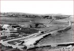
The original plan was to knock up a test track consisting of a run-round loop with a single siding off the loop, and indeed that is what I have started to lay. However I have since developed the idea a bit, so have amended the Templot plan so that the original single loco release point at the end of the loop is now a crossover giving me an extra siding parallel to the loco release, giving me a plan similar to West Bay station at the end of the Bridport branch.

Screenshot 2023-07-04 at 12.53.12.jpg
West Bay Station

My thinking now is that I could eventually incorporate this test track into a wider scenic board, and to help facilitate this potential end game I have re-aligned the original siding so that diverges slightly more to make use of more of the 6" width that I have available.

IMG_4719.JPG
A general overall view of what has been played so far, and also shows how the siding deviates from my original plan. At the time this photo was taken I had not stuck the engine release crossover and additional siding gained in place. As can be seen, my preference is to build my track work in situ, which on a board this size is probably just as easy as building it offsite!

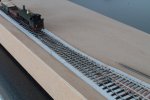
IMG_4720.JPG
Finally, a closer view of the completed turnout built using the various normal, slide and check rail etched chairs available from the Association. Looking at the photo, I realise that I have still to fit 2 chairs this end of the crossing nose, although these will need to be butchered a bit as there isn't enough room for 2 ordinary chairs to fit end to end. One thing that may be noticeable in the above photo is that I am laying my Easitrack sleepers individually (rather than in the panels of 6 that they come on the sprue on) - As this is a test track, I wanted to see if I could lay the sleepers such that I would have prototypical rail lengths with appropriate sleeper spacings.

That's all for now, thanks for looking
Ian
 
Top