Lyndhurstman

Western Thunderer
Linked In
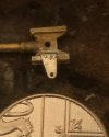
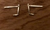
Motion madness strikes again. This week, having cut some rods from solid sheet, and being less than happy with the results, I treated myself to some nickel silver strip from Eileen’s Emporium (very fast turnaround…) and, this afternoon, after battling with the paving slabs in the back garden, I’ve knocked up a couple of combination levers for the Y4 Walschaerts valve gear. Drilled 0.45 mm in three places, to take nickel silver pins. Dimensions taken from the GERS drawings. I made up a couple of union links earlier this week, too. Here’s the beginnings of the knitting having a test fitting.
40CBE494-D95B-4A0F-8DD5-333F4DD210F7.jpeg

Cheers

Jan
 

Lyndhurstman

Western Thunderer
Excellent work how do you centre a 0.45mm drill bit on that a big big magnifier?
Hello @AdeMoore
Thank You. A bit fiddly!

I have a loupe. It a hinged lens in a wire frame that springs on the frame of my glasses. I’ve had it years; part of my toolkit from my time working for HMG.

Stuff this small, I don’t bother centre popping. Just firm pressure on the drill (in a pin chuck - one of the thin long ones, rather than the short stubby ones; I try to minimise any imbalance) until I see swarf appear. If it’s not central, I turn it over and have another go .

Cheers

Jan
 

AdeMoore

Western Thunderer
Hello @AdeMoore
Thank You. A bit fiddly!

I have a loupe. It a hinged lens in a wire frame that springs on the frame of my glasses. I’ve had it years; part of my toolkit from my time working for HMG.

Stuff this small, I don’t bother centre popping. Just firm pressure on the drill (in a pin chuck - one of the thin long ones, rather than the short stubby ones; I try to minimise any imbalance) until I see swarf appear. If it’s not central, I turn it over and have another go .

Cheers

Jan
Ah I was thinking mini drill or drill press yes now you mention it think I did similar on my stalled Jane No.5 build, memory fades fast!
 

Lyndhurstman

Western Thunderer
More Motion Madness

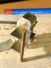
The first of the crossheads (Comet, lost wax casting) has been the focus this last evening. In reality, the bracket (I’m not sure it had a name - when I learned for my Drivers exam at Toddington, we just had ‘crosshead with pin’ to describe it - but The LMS diagram in the Black Book call it the ‘crosshead arm’) should extend over the whole face of the crosshead, but that would have rendered the finesse of the casting void. So a bit of 0.012” nickel silver bent in my Hold & Fold, and soldered onto the crosshead with Fry’s solder paint. After that, holes were drilled to take two pins of 0.3 mm brass. These too have been soldered in. Hopefully, it won’t be going anywhere - except in a reciprocating stylie, of course..

A250CBFF-AE02-4CD9-874F-048894607B2B.jpeg

Cheers

Jan
 

Lyndhurstman

Western Thunderer
Wrapscallion
Mischievous metalwork moment. After a couple of hours of trying to fit the cylinder wrapper on over the weekend, I conceded defeat, pulled what I’d done apart, cleaned it off, and took the evening of.

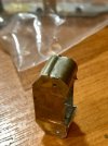
Yesterday, I tried another tack. Using a bit of a jig, and after a glass of red wine, I went at it again, starting at the bottom, and tacking as I went. The brass sheet (0.005”) was warmed up over the gas prior to. It went quite well, although I’m a tad disappointed with my attempts to creat the channel between cylinder barrel and valve chest; the weekend version was better, but it wouldn’t let me solder it up.

83D5ADED-6DA0-491E-A94A-AABB0677FC8F.jpeg
Tonight, the other side did what I asked of it. I used the Hold & Fold to make the delineation, but I also felt more confident second time around. I think I’ll leave it, now. I have slide bars and glands various to twiddle with. Oh… and I’ve got to cut it in half….
EEFA4473-68DE-444B-BBBF-D10936EFEDB2.jpeg

Cheers

Jan
 

Lyndhurstman

Western Thunderer
Slip Sliding Away.

More Will It Won’t It Work at Watkins Wharf as we experimented with adding one set of slide bars to the cylinders.

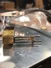
The slots in the packing gland were opened out to accept the slide bars - offcuts of nickel silver sheet - with a junior hacksaw blade (a lovely coincidental thickness moment) and the whole lot soldered up with 188 solder paint. It was then cleaned up, and transferred onto the back of the cylinder, itself held down in the RSU workplate (a grandiose term for a bit of stainless steel on an offcut of garage door frame) being centrally located with a suitably-sized drill.

A wick dab of full power with the RSU saw everything fixed as it should be. And - an added bonus - the crosshead slides smoothly to and fro..
E60288B1-1394-442C-8895-17AB499541A7.jpeg
… tiny steps. Something like stop motion, you might say…

The slide bars are overlong (cue Foo Fighters…) as I want to try and locate them within the motion bracket (rather than butt joint them to it).

Cheers

Jan
 

AdeMoore

Western Thunderer
I struggled big time with this on my old Wantage no5 gave up actually!
Im trying to visualise your stainless steel garage door frame RSU process.
Someone else on my thread back then advised silver soldering.
Interesting stuff and a nice outcome.
Cheers for sharing.
 

Lyndhurstman

Western Thunderer
Hi @AdeMoore
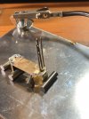
Thank you. I’d video it, but I’ve no hands left! :) The RSU is able to place a very high heat into a very small area, very quickly. Literally one second of full power is enough on the top of the packing gland is enough to make the solder paint flow underneath. And a careful dab even allows a slight movement of one of the slide bars if the point of the electrode is placed on the joint. Ask me how I know…:)
31AC26A9-123D-4765-891A-DA0ECBBCB8E1.jpeg
… the other ‘must have’ in my setup is some decent magnets.. Everything workplate-related (barring the wooden remnant of the garage door frame ) was sourced via EBay.

Cheers

Jan
 
Last edited:

AdeMoore

Western Thunderer
Hi @AdeMoore
Thank you. I’d video it, but I’ve no hands left! :) The RSU is able to place a very high heat into a very small area, very quickly. Literally one second of full power is enough on the top of the packing gland is enough to make the solder paint flow underneath. And a careful dab even allows a slight movement of one of the slide bars if the point of the electrode is placed on the joint. Ask me how I know…:)
View attachment 155688
… the other ‘must have’ in my setup is some decent magnets.. Everything workplate-related (barring the wooden remnant of the garage door frame ) was sourced via EBay.

Cheers

Jan
Gotcha Jan picture paints a 1000 words and all that.
Cheers.
 

Lyndhurstman

Western Thunderer
A Couple Of Bores
Small Progress on the cylinders.
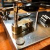
I’ve added the steam valve packing glands. These are two lengths of Albion Alloys brass tube; one a sliding fit over the other. The smaller diameter (1.3 mm) goes all the way through to the inside front of the cylinder cover (you can see it inside on the right) and a 2 mm long collar fits over this on the outside. I did it this way to give me some meat and solidity to the location on the outside, so I could solder it; trying to put just the collar on was less than successful!

A few seconds of Medium from the RSU was enough to let the solder paint do it’s thing. No issues with everything coming apart yet; which is a selling point of an RSU.
CA767044-BE10-4CE9-888F-1D80D4B3AC5D.jpeg

Cheers

Jan
 

Lyndhurstman

Western Thunderer
Weight for the Spokes, Man
A little plastic persuasion tonight.
The Y4 had chunk aplenty. And none more so than in its ‘feet’.
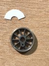
Mike Sharman’s book has these locos as having 3’10 10 spoke wheels. We couldn’t find anything to match, so we’ve gone with Gibson 4’ 10 spoke - what’s 2” between friends? The J67/9s had these; they were being held in Stores for a couple in the Future Projects portfolio, but they won’t be needed for a while yet - especially as we are seemingly disciples of Dr Fitzunstartz.

We tried an OLFA for this, but mailed fiserably. We believe the device is better suited to a larger radius - not the 7.1 mm (OANAD) we we’re hoping for. So in the end, we went with dividers, scissors, and file.
185AF2F6-8981-4703-A672-6FD9D51E3192.jpeg
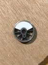
The weight was held with a dab of superglue, applied with a cocktail stick, in order to stop it floundering all over the plaice.

2700167F-377A-4BAC-A5E2-2A0E3C8CF5F9.jpeg
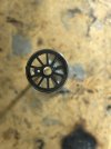
After the glue had gone off, the rear side was treated to a couple of drops of Gorilla glue - various folk Over There mentioned epoxy, but we are not fans. It’s messy, and tends to get everywhere. A bit like Beryl.

The wheel was then placed on another cocktail stick, weight side down, to dry.
2A32469D-2FDF-492D-B571-D38F50C92381.jpeg
Two down, two to go.

Cheers

Jan
 

Dave Holt

Western Thunderer
Jan,
Although I'm not familiar with your prototype, on locos thet I am familiar with, having built-up balance weights, the ends of the outer plates invariably coincide with the spokes rather than ending between as you have modelled them. Just a thought.
Dave.
 

Lyndhurstman

Western Thunderer
Jan,
Although I'm not familiar with your prototype, on locos thet I am familiar with, having built-up balance weights, the ends of the outer plates invariably coincide with the spokes rather than ending between as you have modelled them. Just a thought.
Dave.
Not according to the GERS drawing, Dave. And the weight appears shifted slightly in a clockwise direction, giving more of a gap at the back. Of course, I should check the photographs (of which I have a bucketload) but I’m not sure I want to now! :)

Cheers

Jan
 

Dave Holt

Western Thunderer
Yes, looking back through your thread, I now see the drawing shows how you have them, so prototype rules OK. Good job you're building it, not me, because I would have made a boo-boo.
By-the-way, I do admire how you managed to drill the holes right in the middle of the valve gear rods. However hard I try, I always seem to end up with some off-centre holes.
Dave.
 

Lyndhurstman

Western Thunderer
Yes, looking back through your thread, I now see the drawing shows how you have them, so prototype rules OK. Good job you're building it, not me, because I would have made a boo-boo.
By-the-way, I do admire how you managed to drill the holes right in the middle of the valve gear rods. However hard I try, I always seem to end up with some off-centre holes.
Dave.
Hi @Dave Holt
Thanks. I didn't bother with centre popping. I just used a sharp drill, and took it very slowly. There was a degree of skid, but I just turned over and started again. The interesting bit was drilling out the 1 mm valve crosshead for a 0.8 mm valve spindle .

Cheers

Jan
 

Dave Holt

Western Thunderer
In situations like that, I "turn down" the end of the spindle by holding in a pin chuck and rotating/drawing against a sharp cornered file to produce a millimetre or so of reduced diameter. You can then drill a smaller hole, say 0.5 or 0.6 mm in that case, in the mating part.
Dave.
 

Lyndhurstman

Western Thunderer
In situations like that, I "turn down" the end of the spindle by holding in a pin chuck and rotating/drawing against a sharp cornered file to produce a millimetre or so of reduced diameter. You can then drill a smaller hole, say 0.5 or 0.6 mm in that case, in the mating part.
Dave.
Thanks @Dave Holt
I drilled the block 0.45 mm initially (it’s only 3 mm long) and went in from both ends. Then - when I realised I’d underestimated the size of the valve spindle - opened it out to 0.8 mm. Good job my initial excursions were not off centre!

Cheers

Jan
 
Top