Gadgie’s workbench (EM)

Gadgie

Western Thunderer
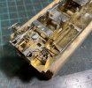
I’ve finished the injector pipe work, and the vacuum pipe connection to the tender. For a moment I was tempted to drill out the overflow pipes, but wiser counsel prevailed…

EC3A3FAD-0599-4D51-A2E0-1CB5A090417B.jpeg

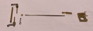
I have also assembled the parts for the reverser. Another very pleasing set of components to put together.

8363E6B4-5F1C-4C62-878B-574C9A0E3EFE.jpeg

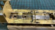
Here they are, placed loosely in position.

C7FAA497-B64D-4289-8717-1A02CFF651C0.jpeg
All very satisfying.

Richard
 

34091 Weymouth

Western Thunderer
I’ve finished the injector pipe work, and the vacuum pipe connection to the tender. For a moment I was tempted to drill out the overflow pipes, but wiser counsel prevailed…

View attachment 173260

I have also assembled the parts for the reverser. Another very pleasing set of components to put together.

View attachment 173261

Here they are, placed loosely in position.

View attachment 173262
All very satisfying.

Richard

Bloody hell Richard,

That is a work of art. Beautiful modelling, I've never been brave enough to do a Bradwell wd.

Si
 

Gadgie

Western Thunderer
Thanks Si — though to be honest it is just a question of following the instructions, which are mostly helpful, and doing one thing at a time. Ah yes, time. It pays not to hurry with Dave’s kits, but they do go together sweetly. You’ve made a great job of the Consett A class kit, and I wouldn’t rule out a Bradwell kit.

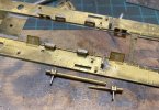
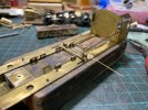
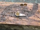
So the instructions are mostly good, but they don’t explain how to fit the reverser rod castings to the footplate. I don’t possess an RSU so this was going to be tricky. I decided to drill the bottom 0.6 mm and solder in a short length of brass rod. Each bearing also has a short length of 0.9 mm rod soldered in, and those locate in a length of tube that represents the reversing rod. I then drilled a couple of 0.6 mm holes in the footplate to locate the bearing pegs — hopefully visible in the pic.

CA5857D4-6E0B-47BB-83F2-9700A6197C28.jpeg

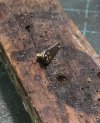
The bearings were then soldered from underneath, thankfully without any untoward disintegration. I have also assembled the reach rod, which appears to be about the right length (phew), though just propped in place here for the moment.

E6C31694-2573-4747-BC01-91391990234E.jpeg

There’s some big jobs looming. I’m still putting off fitting the valve gear. It is all made, forked joints and all, but awaiting the happy conjunction of a lengthy block of uninterruptable time and the right mood. And probably a stiff drink as well …
Richard
 

34091 Weymouth

Western Thunderer
Thanks Si — though to be honest it is just a question of following the instructions, which are mostly helpful, and doing one thing at a time. Ah yes, time. It pays not to hurry with Dave’s kits, but they do go together sweetly. You’ve made a great job of the Consett A class kit, and I wouldn’t rule out a Bradwell kit.

So the instructions are mostly good, but they don’t explain how to fit the reverser rod castings to the footplate. I don’t possess an RSU so this was going to be tricky. I decided to drill the bottom 0.6 mm and solder in a short length of brass rod. Each bearing also has a short length of 0.9 mm rod soldered in, and those locate in a length of tube that represents the reversing rod. I then drilled a couple of 0.6 mm holes in the footplate to locate the bearing pegs — hopefully visible in the pic.

View attachment 173319

The bearings were then soldered from underneath, thankfully without any untoward disintegration. I have also assembled the reach rod, which appears to be about the right length (phew), though just propped in place here for the moment.

View attachment 173320

There’s some big jobs looming. I’m still putting off fitting the valve gear. It is all made, forked joints and all, but awaiting the happy conjunction of a lengthy block of uninterruptable time and the right mood. And probably a stiff drink as well …
Richard

Thanks Richard.

It's looking lovely, the detail is superb. I know what you mean about having a good stretch to do some jobs. I'm like that when I'm building a chassis, I like to have it built to a basic chassis & rolling so I know I can breath a bit afterwards. I don't like getting a big job 3/4 finished.

I'm looking forward to seeing this one finished, it's the first wd I've seen built from daves kit.

Si
 
WD valve gear

Gadgie

Western Thunderer
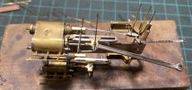
I felt ready to begin assembling the valve gear this evening. A grumpy day at work dealing with a series of annoying and unnecessary administrative tasks, followed by a cycle ride home (uphill) in the pouring rain, and an hour helping my neighbour fix an errant gutter by torchlight, seemed somehow to produce the right level of calm.

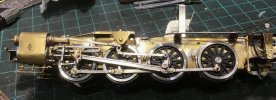
So here is the port side, partly assembled with outward pointing lace pins to check clearances and free movement. All appears to be well. The tricky bit was ensuring enough room in the valve guide for the combination lever and valve rod to move freely. It would have been much easier to open out the castings before fitting them in place. My grandfather’s rather nice set of riffler files came to the rescue, but it was a tricky and time consuming job, made easier by some favourite Waterboys tunes.

17F9D7E5-42ED-4DCF-8E11-3718174E608E.jpeg

Richard
 

Gadgie

Western Thunderer
So...
With a torch in your pocket [...] you climbed on the ladder?
Not quite ...

Our neighbour is an orthopaedic surgeon, who has all too often had to deal with the consequences of dodgy working at height. As a consequence he normally has a "no ladders" policy, but we needed to take action because a detached downpipe meant that rainwater from the front of his house was running into his cellar instead of the drain. I have a long ladder, so he used that, with me at the foot and our other neighbour providing illumination with a small but very bright LED torch. Apart from getting soaking wet, no dramas ensued and the downpipe is now secured.

Looks like more rain for the weekend here, which hopefully means less garden tidying and a bit more time on the WD valve gear :).

Richard
--
 

Gadgie

Western Thunderer
Thanks!

There were some photos of 65871 under construction on RMweb, but I expect they have all gone now. It’s in pieces at the moment; the DCC chip blew up at Expo EM, and I haven’t got round to investigating why.

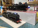
I think the extended smokebox of the formerly superheated J27s gives them a more thuggish appearance though compared to the regular ones. Here’s an old photo of 65871 pre-weathering (and pre buffers) alongside 65817, which is an out of the box Oxford Rail model.

0EEDE2F3-3114-4343-B14B-C55CF802B924.jpeg

The Oxford Rail model compares pretty well to the Bradwell kit, from a distance anyway. The main shortcoming to my eyes is under the boiler, where the solid chassis block is all too obvious.

It will get EM’d at some point, and I’ll wish I was the brakeman on a hurtling fevered train …
 

Gadgie

Western Thunderer
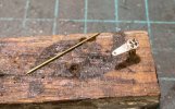
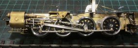
A little more progress to report. Both sides of the valve gear have been assembled, bar fitting the return cranks. I drilled the return cranks for the four rather prominent bolts, and used these to drill holes in my favourite bit of wood. The remains of four dressmaking pins snipped off during assembly of the valve gear were then inserted in the holes, soldered to the return crank, and filed down.

996AB6B6-5BE8-4580-BD94-D000EF3CEDA3.jpeg

I have used Markits “deluxe” crank bushes with 14BA bolts, so the next step was to fit a crankpin bush to the return crank, the trick being to locate it in such a way that when tightened over the connecting rod it tightens at the correct angle.

2099DA25-C427-46C0-A8BF-3974360072FC.jpeg

Initially all was well.

9138CE63-9A3D-469B-B870-E16AF68CA6EF.jpeg
But then …

6771EFB9-F372-40C1-8AAE-9513E80CE8F8.jpeg

It turned out that solder had entered the end of the crankpin bush. Screwing down the crank broke the solder joint. So out with a 14BA tap, and a repeat performance, this time with a bolt inserted to deter solder. This appeared to cure the problem.

E066559D-CECD-48D0-B651-7FDE645B6EDF.jpeg

It runs quite nicely under finger power. So now for the starboard side …

Richard
 
Last edited:

34091 Weymouth

Western Thunderer
A little more progress to report. Both sides of the valve gear have been assembled, bar fitting the return cranks. I drilled the return cranks for the four rather prominent bolts, and used these to drill holes in my favourite bit of wood. The remains of four dressmaking pins snipped off during assembly of the valve gear were then inserted in the holes, soldered to the return crank, and filed down.

View attachment 174409

I have used Markits “deluxe” crank bushes with 14BA bolts, so the next step was to fit a crankpin bush to the return crank, the trick being to locate it in such a way that when tightened over the connecting rod it tightens at the correct angle.

View attachment 174410

Initially all was well.

View attachment 174411
But then …

View attachment 174412

It turned out that solder had entered the end of the crankpin bush. Screwing down the crank broke the solder joint. So out with a 14BA tap, and a repeat performance, this time with a bolt inserted to deter solder. This appeared to cure the problem.

View attachment 174413

It runs quite nicely under finger power. So now for the starboard side …

Richard
That's looks super Richard,

How do you keep those gibson wheels sp shiny? I popped mine on the RSH & they are already getting a slight rust coat on. I keep the parts as clean as I can too during assembly.

Si
 

Daddyman

Western Thunderer
That's looks super Richard,

How do you keep those gibson wheels sp shiny? I popped mine on the RSH & they are already getting a slight rust coat on. I keep the parts as clean as I can too during assembly.

Si
Could be a reaction to the flux you're using, which will inevitably get on your fingers.
 
Last edited:

Gadgie

Western Thunderer
Could be a reaction the flux you're using, which will inevitably get on your fingers.

Yep -- this could be the reason. Also liquid flux can spatter quite a distance when it boils vigorously.

I use Fluxite paste flux for assembling loco kits, mostly out of habit. It leaves a sticky mess that attracts filings and other gunk, but doesn't rot tools or wheels as much as liquid flux can. The sticky mess can be removed with hot (almost boiling) water and detergent in an ultrasonic cleaner -- and the cloud of goo that erupts from a model when the ultrasound is turned on can be very pleasing.

Having said that, there are little spots of corrosion on the wheels and I remove them from time to time with a glass fibre stick. When coming back to the kit after a six month or so break over the summer I also discovered that the previously quartered wheels were very stiff. Gloom descended as I tried to figure out what had happened to move the wheels on their axles. Then I realised that I had not applied any lubrication and a couple of the steel axles were very slightly corroded in the brass bearings. The problem was very easily fixed with lubrication and gently cleaning away the spots of corrosion, resulting in a smoothly running chassis.

Richard
--
 

34091 Weymouth

Western Thunderer
Yep -- this could be the reason. Also liquid flux can spatter quite a distance when it boils vigorously.

I use Fluxite paste flux for assembling loco kits, mostly out of habit. It leaves a sticky mess that attracts filings and other gunk, but doesn't rot tools or wheels as much as liquid flux can. The sticky mess can be removed with hot (almost boiling) water and detergent in an ultrasonic cleaner -- and the cloud of goo that erupts from a model when the ultrasound is turned on can be very pleasing.

Having said that, there are little spots of corrosion on the wheels and I remove them from time to time with a glass fibre stick. When coming back to the kit after a six month or so break over the summer I also discovered that the previously quartered wheels were very stiff. Gloom descended as I tried to figure out what had happened to move the wheels on their axles. Then I realised that I had not applied any lubrication and a couple of the steel axles were very slightly corroded in the brass bearings. The problem was very easily fixed with lubrication and gently cleaning away the spots of corrosion, resulting in a smoothly running chassis.

Richard
--

I've just discovered that the splatter from boiling flux has attacked the gearbox. I'm currently rebuilding it. I'll give the fluxite a go & see how I go.

Si
 

34091 Weymouth

Western Thunderer
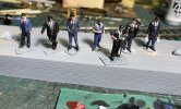
Last weekend we had our last South Pelaw running session before the Manchester show, and the layout felt a bit devoid of human life. So a package arrived this morning from the nice folk at Modelu, and after a fun evening painting we now have a few blokes — gadgies even — to plonk on the layout.

View attachment 175155

Richard

I shall come over & say hello Richard. I. Very much looking forward to seeing pelaw.

Si
 
Top