Finescale - of a sort?!

Peter Insole

Western Thunderer
Ok, so It's taking a little bit longer than expected, but the bodging fun has been steadily continuing! Of course, it goes without saying that I have made extra work for myself in a few areas, as usual, but at least I have some confidence that the finished article will be a bit more bombproof this time around!
hSAM_yx9005.JPG

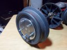
The trouble with this kind of engineering (reverse?) is having to find solutions to awkward problems: There always seems to be something that gets in the way of either holding a piece securely, the drill chuck, or in this case; being able to cleanly draw a file across a surface to clean up!

I probably should have taken the apparently easier route of soldering plain studs into the discs, and then attaching nuts from behind... but ended up convincing myself that there was insufficient space down between the "spokes", so opted instead for large headed machine screws - each of which had to be cut only fractionally over length before fitting, in order to reduce the amount of metal that would need to be filed back to flush. All because when I had measured the depth required for the steel centres, I had assumed (yes I know!) that the tyre rims would be the same as the hubs - whereas, it subsequently turned out that the former projected slightly further outwards!

Oh well... I would just have to resign myself to an awful lot of riffling!

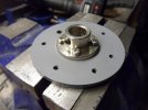
Before tackling that, I wafted some primer on the rear face of the discs to reduce the risk of corrosion between the mild steel and plastic:
hSAM_yx9033.JPG

I know these are only supposed to be a temporary fix... but such things have a habit of becoming rather more permanent around here, so it seemed to be a sensible precaution!
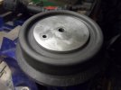
hSAM_yx9035.JPG

Cutting threads with cheap, bog standard taps meant that it was almost impossible for me to hide the screw ends... but nothing a swipe of filler and some thick lumpy paint wont cover (?).
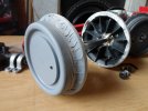
hSAM_yx9041.JPG

I just remembered in time to drill the coned lathe centre points in the axle ends... before getting the jolly paint brushes out!
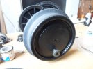
hSAM_yx9043.JPG

Apart from a couple more coats of "pretend"; (LYR specification) Japan Black... and the eventual arrival of the essential pair of new "take-up" bearings... (come on please Mr. Mostman Pap!) the leading set are ready for installation.


Pete.
 
Last edited:

Brian McKenzie

Western Thunderer
Pete, I recommend filling the back of the wheels with some sort of 'bog' compound ( or even a cement mix :eek: ) right down to the axle.
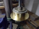
While your bolted metal flanges are good and strong to the thin face of the wheel, the ribs at the rear no longer contribute much rigidity, since being cut away from the original hub.

(A ring of wire threaded through the ribs might be good 'reinforcement' for any fill.)
 

Peter Insole

Western Thunderer
Thanks for the tip Brian, I had always intended to back-fill those wheels for precisely that reason, but could not quite make up my mind what to use! A pouring resin of some sort would seem to the obvious choice, although I have also toyed with the idea of using (readily available) fiberglass that could be layered between the spokes and built up around the hubs to set them solid.

Strangely, I am glad I didn't take any such action at the time, because the current modifications, that have proved to be necessary, would have been almost impossible!

In typical fashion, I allowed impatience to determine fate by operating the loco well before completing many fundamental tasks! Such an approach has however, along with pushing at every boundary and challenging all accepted wisdom along the way, provided even more surprising revelations.

Despite the rather obvious logic that the spokes, combining at the original hubs, would have provided the maximum amount of strength - it was those hubs that quite rapidly failed in service! The peculiar, dark grey plastic used does have a rather convenient trait, in that it shows clearly where areas of stress are occurring by showing lightened, witness marks - some time before it actually breaks. I take some comfort from observing that there are no such marks appearing, nor has there been any apparent deflection on the rear driving wheels - that incidentally had already been modified with metal flange centres, and then subjected to two seasons worth of some seriously punishing service!

I can only guess that what remains of the spokes after the centres have been hacked away are still acting as fillets on a bracket - and that the load stresses continue to be sufficiently spread into the faces when in service?

This particular upgrade job is supposed to be only a temporary solution - albeit with no specific time frame in mind, so I have baulked at the prospect of spending too much money on it. Ironically perhaps, the cost of materials, (resins and suchlike) including what has already been spent, is equal - if not greater than the expense of simply replacing the whole lot with "proper" steel wheels anyway!

Having said all that, while noting that the comment was probably a bit tongue in cheek - I actually quite fancy the idea of using something cement based (or similar?) for a precautionary backfill!

I will have to be very careful with the design for applying any variety of reinforcing filler though - as another peculiar problem is that the wheels must remain easily removable from their axles - as that is the only way to install or remove the motor/gearbox at the rear, and the sealed, ball race, inside bearing units on the leading pair!

Pete.
 

simond

Western Thunderer
Pete

I’d very strongly suggest you don’t pour a fibreglass resin or epoxy into the wheels. The polymerisation reaction is exothermic and if it’s a big volume or quite thick (it looks like both) it’ll get ruddy hot!
You can certainly do it by layering
 

Osgood

Western Thunderer
One solution might be an anchoring type of polyester resin? Depends what you want the filler to achieve I guess.
I believe it was used to anchor those hold-down bolts into the concrete for the station building?
Available in a few strength grades so go for the stronger one.
Some available in 300ml cartridge for use in a standard gun (you can just get away with using a standard gun), some in 410ml cartridges for use with a dedicated gun (that costs £40 odd).

This is the one I use (I think it is the stronger type) - here in std 300ml form:
 
Last edited:

Peter Insole

Western Thunderer
Speeders, Wagons and whatnot have been something of a distraction, so not a lot happening on the Horwich loco of late! I felt a short break from the heavier metalwork would be welcome, and an opportunity arose much sooner than expected.

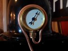
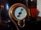
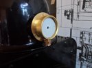
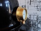
I had always fancied having a battery charge indicator on the locomotive - but definitely not one of the commonly available, digital, pretty coloured bright lights variety! Such a fitting would be appear to be totally inappropriate, as well as particularly difficult to hide on a steam engine - imitation or not! My preference would be for a traditional analogue type, and that if it could be provided with a modified dial, it might plausibly masquerade as a conventional steam pressure gauge? The original was a large - and rather obvious affair attached to a wooden pattress mounted on the dome.

Despite the generous proportions of the prototype however, I found that all of the meter fittings available (either round or square faced) were produced for a standardised, two inch panel mounting hole! Without looking ridiculous, my gauge could not exceed at a maximum one and a half inches of the outside diameter at the bezel. While I do understand how the old mechanism works, I have never taken one of those instruments apart before, so had no idea of the internal proportions - and whether or not they would actually fit in a reduced drum fitting? Also, as the mechanical type are now almost completely superseded by customer preference for flashy, digital technology, they have become something of a rarity - complete with premium price tag attached! Considering that cost, I was not sure that taking a punt was worthwhile for the time being, so shelved the idea.

Then the other day, a friend was clearing his shed and found two of them! What is more, both were rated at 12v, and after a successful test, he asked whether they might be of use for our railway! I willingly accepted one with a slightly tattier casing, on the clear understanding that I may carry out investigative surgery on it!

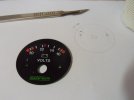
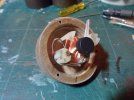
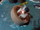
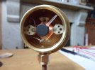
Some quite savage butchery was required to break through the outer shell, but afterwards I was hugely relieved to find that the internals were still intact - and sufficiently minimal for our purposes!

hSAM_yx9174.JPG

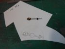
Although I would have been prepared to accept an off-centre needle, fortuitously the magnet and mountings will permit relocation to a more conventional position:

hSAM_yx9175.JPG

I cut a disc from white plasticard, but think that it could do with being a bit thicker to nearer match the rigidity of the original, printed acrylic one?

Don't worry, I fully intend to replace those (now) huge, awfully ugly screws with some slightly more subtle countersinks - along with a new, and appropriately slender pointer as well!

hSAM_yx9176.JPG

That will be a fun bit of micro surgery to come - along with doing some artwork for the new dial - and working out how on earth to make a nice, brass bezelled and flanged drum to fit it all in?!

Pete.
 

Osgood

Western Thunderer
Well now..........

Not wishing to get your hopes up, but I believe some oxygen / acetylene / propane regulator gauges were 1 1/2" dia rather than the more usual current 63mm dia. - in fact some still are but sadly not of brass construction, e.g. Harris.

Just where you might find one is another matter, although perhaps a local gas welding / cutting gear supplier might have a box of scrap regulators?
 

Peter Insole

Western Thunderer
My sister works in the NHS, and has told me about a particular surgeon that she has occasion to assist in theatre. He has a very noticeable, and apparently persistent tremors, so after he has done his pre-op rounds, the staff have to quickly follow and desperately try to reassure many terrified patients; that not only is he one of the best in the country - but the moment he picks up a scalpel, his hands become steady as a rock!

Oh well, I suppose that in my case; after having spent a lifetime perfecting the art of waywardness it should come as little surprise that the effect of my own affliction would be so opposite?!

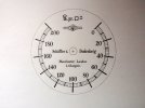
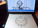
After a more satisfying dive down yet another research rabbit hole, the effort of making a finished piece of artwork was a trial that took a whole day - and well into late evening yesterday:

hSAM_yx9181.JPG

The result is I fear a bit rough round the edges, bearing in mind that I did it large enough to handle on an A4 sheet, but I do take some comfort in the knowledge that when the copy is reduced right down to 1 1/2 inches diameter, most of the detail will be lost in ink-jet dots anyway?!

At least I can be reasonably confident that the design has some historical accuracy, and that while no-one else will probably ever be able to see it, I will henceforth be aware that the work was diligently done.

In the absence of any sufficiently decent footplate views recorded of the locomotives in service, perhaps the most curious, and helpful clue as it turned out, to the type and identity of the original pressure gauge manufacturer was fortuitously hinted at by an astute Horwich draughtsman! While producing a basic, "general arrangement" drawing, it was only really necessary to have described the outer shape, with perhaps no more than a hint of purpose by adding the representation of a pointer, but instead he chose to carefully describe the particular - and what appears to be a peculiarly inverted gauge - as well as a distinct feature of the "chapter ring"!

What a champion!

hSAM_yx9180.JPG

After much delving, I have come to the conclusion that "Schaffer" was an early patentee of pressure gauges, both of his own "diaphragm", and a version of the more familiar "Bourdon tube" type. Indeed, the somewhat unusual, (to my eyes) and counter intuitive feature of having the ascending scale effectively running from the top right of the dial to left may have been a part of the original patents.

(Hah! So I thought I was wayward?!)

Schaffer's association with Budenberg, led to them becoming one of the largest international suppliers of such pioneering gauges. What is more, the Company set up a significant British operation, and built a factory in Manchester. Perhaps it is not so surprising therefore that Beyer Peacock, as well as the Lancashire and Yorkshire Railway, among others appear to have regarded them as a "local" preference?!

I had mentioned the "chapter ring" - and that was the second clincher in the drawing for me! You might note that the each of the numerically marked increments has a line that extends outwards, to disappear behind the bezel. That feature was also a distinct trademark of S and B, and was maintained - without imitation - right up until relatively recent times - and indeed long after the Budenberg Gauge Co., (as it became after 1914) had adopted more "conventional" designs!

A final piece of evidence came to light at the end of my research:

The gauge currently fitted to "Wren" on display at the NRM is sadly a result of theft, perpetrated in the 1960's while the loco was stored in the Horwich paint shops, and is a very poor quality, almost pathetic attempt at fakery, so is desperately misleading!

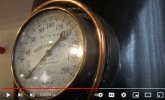
The gauge on Beyer's own little "Dot" at Tywyn is much more interesting - as a screen-grab from a video clip now reveals:

SAM_yx9178comp_Schaffer and Budenberg on DOT.jpg

Such a precise instrument is extremely unlikely to be the original one fitted in 1887, but from the style of the markings, can still be identified as a beautiful, early example!

Although barely visible in the latter image, (see first one in this post) I particularly like the rendition of the "lbs" symbol - where a swirling line from the lower case "b" forms the final "s"! I have not seen that used before, and again assume that it may have been another Schaffer signature?!

Pete.
 

class27

Active Member
Oh how I wish I could work as rough as that.....
I guess pressure gauges would get swapped around as they would need testing and calibrating periodically. Much more so towards the end as parts would get swapped around to keep things going.
We had a Test Rig at work which had 2 quite stunning Budenberg Gauges on it at about 10" needless to say it went in the skip without them. No wonder I never seem to have any space here.
 

Peter Insole

Western Thunderer
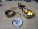
The little gauge arrived by courier this afternoon, and was immediately dismantled with a haste indecent... and a small screwdriver as well of course!

hSAM_yx9183.JPG

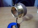
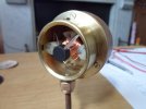
There was a slight risk that the barrel and bezel might have been plated, but I'm very happy to report that both are solid brass pressings. It is quite clear that it was originally lacquered all over - but that someone had at one time fallen into the fairly common trap of applying an abrasive metal polish - and then discovered to their dismay that they would have to keep re doing the buffing job for ever thereafter!

The patchy tarnish was still quite shallow, and so the thing has already started to shine up a treat:

hSAM_yx9184.JPG

There are some scratches, knocks and dings here and there - but I particularly like the look, so will make no attempt to polish them out myself.

Now the fun can really start; making up a new, dummy brass flange and a shaped wooden pattress for mounting.

Pete.
 

Peter Insole

Western Thunderer
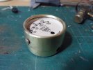
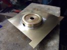
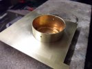
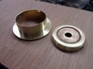
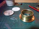
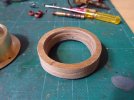
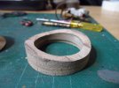
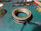
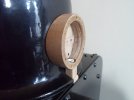
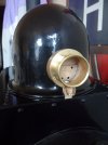
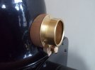
The first thing to do with the gauge was to cut and fit a new brass flange onto the main body.

I decided that in order to avoid distorting the fairly thin tube section when cutting, I could remove the unwanted back only after soldering same:

hSAM_yx9185.JPGhSAM_yx9186.JPG

I was so engrossed with the task of taking out the centre by drilling a ring of small holes, and then steadily filing all round to a really snug fit over the tube, that I quite forgot to document it - remembering my camera only after I had started cleaning up!

As you can see in the first image, I got rather carried away and clumsily applied a bit too much solder on the back! I was however relieved to note that the fit was probably a touch too good, as hardly any had capillaried through to the visible, front face of the joint! Satisfied that the bond was nonetheless good and strong, I started sawing away the plate, and quickly came to the conclusion that whilst the earlier method of drilling a series of holes was more time consuming, it would be significantly less physical effort in the end!

After reaching the rough cut stage, another stroke of luck struck...

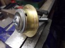
It turned out that one of those old pipe bending mandrels - already adapted for turning the nylon tyre profiles - just happened to be a good fit! Even the diameter of the hole in the gauge back was the nearest imperial equivalent of the metric holding bolt!

hSAM_yx9188.JPG
hSAM_yx9191.JPG

Spinning the flange with fine files and emery to finish was a just a dream!

Slicing the back off was a little more nerve wracking though, as the saw blade had a tendency to snatch on the two partly covered, original pipe entry and exit holes in the tube.

I did manage to get through without losing either my dignity or digits though!

hSAM_yx9193.JPG
hSAM_yx9195.JPG

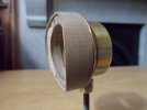
The bezel/cover section really needs to be shortened now - so that the inside edge comes to roughly half the distance between the front of the gauge and the flange - but I don't yet have a clear plan in my head for accomplishing such a fine cut through the flimsy brass this time?!

If I can get that sorted today, following thoughts will have to be focused on the fun of the awkwardly formed pattress!

Phew!

Pete.
 

Peter Insole

Western Thunderer
I chickened out of tackling the wooden pattress yesterday, so started looking at the gauge fittings instead!

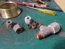
Although it was terribly sad to see our old caravan (container of many memories) being savagely (but efficiently) demolished, I was "allowed" to salvage some bits and bobs that might be useful for the railway! A quantity of copper gas pipe, handily in three different diameters, along with brass tees and nuts were amongst the items selected. The smallest sections for the caravan lights were, according to the Beyer Peacock GA's anyway, of precisely the right scale proportions...

hSAM_yx9196.JPG

The very crisp, unmarked finish under all the crud suggests that these things are unlikely to have been touched since they were originally installed in around 1974?!

hSAM_yx9198.JPGhSAM_yx9199.JPG

Not only do I like the "heritage" idea of having some parts (with all the family connections) living on, but utilising them will save some time and effort too!

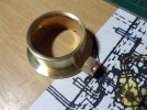
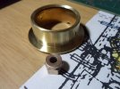
As I didn't want the metal fitting to impinge on the internal space, with the risk of accidental contact with the electrics, I spun off a short length of 6mm brass rod, shaped with a lug at one end and threaded at the other to fit into a sawn off section of tee.

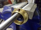
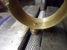
I opened out one of the bezel fixing screw holes (chosen to be the lower) in the main barrel, taking care to ensure the lug was a really tight/force fit. The end of the lug was then burred over to lock it firmly in place:

hSAM_yx9200.JPGhSAM_yx9201.JPG

I found myself wishing again that I had a mini anvil for that awkward task - but the handle of a socket spanner gripped in the vice sufficed - and did the job reasonably enough!

hSAM_yx9203.JPG

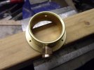
The little monkey of a nut is nice and tight, and isn't going anywhere, anytime soon... well hopefully anyway!

Happy with that now, the pattress problem could not be put off any longer!

With quite a lot of carving in prospect, I would have preferred to fall back on a piece of soft, thick MDF, but could only find a small offcut of ply with sufficient depth for the purpose!

The real thing is a solid block, turned from some variety of hardwood - but the main problem that was exercising me was that mine needs to be hollow throughout, in order to accommodate the greater depth of the mechanism, plus the terminals projecting from the rear! The only method I could imagine with any hope of accomplishment, was to use two hole saws, and by drilling the first (smaller) one part way through - and then taking advantage of the centre bit bore, thus created still being in place, cut the large, outer diameter all the way down.

The remaining block in the middle finally dropped out when the chisel and files reached the shallower cut, as the (steam dome) profile was being shaped out!

hSAM_yx9204.JPGhSAM_yx9205.JPG

The ply is rough old stuff really - and would be quite difficult to disguise, but: I have a plan!

I have still got some nicely flexible 0.4mm ply sheets in stock, and with it's veneer like quality, strips can be layered all round the outside to provide a much smoother finish!

Pete.
 
Last edited:

Peter Insole

Western Thunderer
Well, the aforementioned "plan" seems to have worked - so far anyway!

After cutting out, the largest hole saw that I could find in my toolbox left the outer diameter of the plywood pattress slightly undersize, but I found that two laminations of the 0.4mm sheet brought the surface to a near perfect alignment with the brass flange - just what I wanted!

hSAM_yx9206.JPG

The finish is much better now, and it enabled me to include a shallow lip all round the rear face for invisibly fitting a curved backing plate.

hSAM_yx9210.JPG
hSAM_yx9208.JPG

I used a single layer of the 0.4mm ply, shaped to fit the curved back, and glued some extra strips crossways on the inside to provide a stiffened bar on which to mount the mechanism.

hSAM_yx9215.JPGhSAM_yx9216.JPG

I was slightly perturbed to notice that a small section of the "veneer" had popped just above at the top screw hole, requiring some more glue to be injected and re clamping work. Otherwise, I am quite pleased with how it is all coming together!

I had put the horrible plastic needle back on, partly to protect myself from the sharp pointed end of the slender pivot pin during all the handling required, but also as a clear reminder of the correct reassembly orientation!

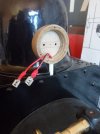
This morning, I thought an electrical test would be a good idea before going any further, just to make sure I hadn't accidentally damaged any of the workings?

hSAM_yx9222.JPGhSAM_yx9224.JPG

It was still working fine - although there's not much to see in a photograph, so I didn't bother to record it!

From rest at zero, (as seen above) to a healthy, fully charged 12v indication, the needle rotates down to pretty much where the 40psi mark will be on the new dial - just as expected!

Pete.
 

Peter Insole

Western Thunderer
I must admit to have been flitting to and fro with the various tasks involved with the little gauge! It is still quite a complicated animal, and thinking of ways to get round all sorts of unexpected problems associated with trying to mix different technologies has been keeping me thoroughly occupied - or maybe that should be distracted?!

While I am still thinking hard about precisely how best to ensure the electrical connections are safely contained (and insulated) at the back of the pattress, I decided to get the relatively straightforward (?) gauge mounting done instead:

Unlike the prototype, where the gauge and pattress were screwed directly onto the dome cover, it had always been my intention to keep all the electrical equipment effectively contained within the "boiler". As the saddle tank, complete with chimney and dome, have to be removable for access, I really didn't want to have any dangling wires to disconnect (or forget to!) when lifting the tank clear! There was also the issue of the copper plumbing, (for both the pressure gauge and the blower) that would have to be left vulnerably unattached, and relying on simple alignment alone.

As a compromise, by permanently fitting the gauge to a fixed part of the boiler - in this case the saddle tank rear flange blanking plate, (acting as something in the style of a cut-down weather board) both the gauge and it's accompanying pipework could be provided with a subtle, and certainly more rigid fixing.

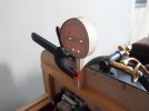
hSAM_yx9227.JPG

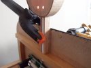
The first act was to drill the bottom of the pattress, and centrally through the horizontal support for the tank back plate to take an electrically inert length of plastic tube.

During that process, I fell foul of my own tendency towards a "belt and braces - and then some" attitude, as well as an innate sense of "rightness"!

I had completely forgotten some additional screws, that a long time ago had been driven into the glued bar and carefully hidden with hard filler! What is more, they were evenly distributed, and one of them was pretty much on the required centre line for the new hole - Well, it would be wouldn't it?! Not fancying the prospect of trying to dig the errant screw out, and then having to clean up the resulting mess, I carefully covered the speed control unit below, hopefully to protect it from any stray, metallic particles falling in, and attacked the exposed part of the screw down the hole with a burr!

It did the trick, and I was able to push the tube all the way through!

The plastic tube fitted firmly, passing through the square slot previously provided in the dome rim, to comfortably carry the wires, but would not itself be strong enough to rigidly carry the weight of the brass gauge. I had considered making some form of metal bracket, but then realised that at the top end would fall rather close to the electrical terminals. Fine under normal circumstances I would assume - but what if the gauge copped an accidental wallop?!

I feel that a bit of Birch ply boxing-up would be a sufficiently sturdy - if rather clunky obtrusion - and once painted gloss black to match it's immediate surroundings, it might more or less disappear behind all the shiny brass and copper fittings anyway?!

hSAM_yx9234.JPG
hSAM_yx9235.JPG

Adding another strip to close the box would hinder closing the saddle tank, so I intend to squeeze some epoxy into the gaps to further strengthen the whole assembly - and especially at the joint with the pattress.

(A couple of wee panel pins, driven part way into the pattress adjacent to the tube, and with their heads set in the resin might help - just to make sure?!)

hSAM_yx9238.JPGhSAM_yx9240.JPG
hSAM_yx9241.JPG

There are probably a dozen better ways to have gone about this job, but I'm hoping to get away with it again!

I trust the twinkly union nut is already helping the bloc to play a game of peek-a-boo?!

Pete.
 
Last edited:

Peter Insole

Western Thunderer
Bit by bit, the gauge is coming together now.

A couple of coats of gloss black on the pattress does seem to have done a fairly reasonable job of disguising the bracket, to the point where I hope it will be barely noticeable - at a distance anyway!

hSAM_yx9248.JPGhSAM_yx9249.JPG

In the end, I decided to use a "hot knife" riveting process, using some old plastic kit "tree" to fit the dial onto the mechanism, rather than trying to find some countersinks of an appropriate size, and then run the risk of splitting the rather hard, brittle plastic mounting flanges when driving them home. There is also less likelihood of any tarnish or other type of corrosion leaching through the intended paper label when it is glued on the front.

The long tails of the original poles will need to be cut back close to the nuts, and then they will, along with the exposed terminals, have to be suitably insulated! Accidental contact with those points, at a potential of 20A, exposed whenever the saddle tank is opened is just not acceptable!!

hSAM_yx9250.JPG

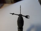
While still thinking about that problem, I turned my attention to the distinctive little pointer:

The original one from the electric gauge was a far too large - and moulded in a clear acrylic, with refractive shaping for illumination, so was completely unsuitable for modification, while the one from the 1950's job was made from brass, and nicely delicate to boot, but again was too long, being proportioned for an off centre pivot.

I really didn't fancy attempting any cut-and-shut operations on the latter, let alone trying to shape up such a fiddly item from scratch out of wafer thin brass sheet! I thought I might try my luck with some 0.10mm styrene instead:

hSAM_yx9243.JPG

Mindful that the material, without bracing will have little or no structural integrity, and indeed may well warp when exposed to direct sunlight, I felt it was at least worth having a go - if only as trial piece for the time being?!

hSAM_yx9245.JPG

The first coat of matt black showed up all the fluffy edges, that were far too small for me to see when working on it - but once the paint has hardened it should be slightly easier to clean up?

I shall mix some dark shades of gloss enamel to try and mimic the usual "blueing" effect found on most similar instruments.

hSAM_yx9253.JPGhSAM_yx9254.JPG

The new pointer is still a bit on the chunky side - but I'm not quite sure if I dare removing much more material without it falling apart in my fingers?!

Initially pleased with the result, I must admit that nagging doubts remain, so the jury is still out for more deliberation!

Pete.
 

Peter Insole

Western Thunderer
Thank you Tony for your encouragement!

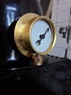
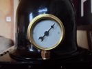
The pointer is still holding out after I had another go at refining and thinning it down a bit more, I think that the promised mixture of "blue" has possibly helped to reduce the overly heavy appearance by a tad too - although that is not particularly obvious under artificial lighting in this evening's photographs?!

hSAM_yx9258.JPG
hSAM_yx9261.JPG

Although I had an appointment for this afternoon, I still managed to get the tricky pipework done!

The one above is the second try - and I very nearly lost it again on the tight return to the union nut! This recycled gas pipe is surprisingly thin walled, and despite going steadily after repeatedly annealing, the tube was on the point of collapse.

Apart from that, it came round everywhere else quite nicely.

It is just a slight shame that while the dimensions of the tube are exactly as reproduced on the Beyer Peacock general arrangement drawings, seeing it finally plumbed in clearly reveals that the pipe diameter is at least one quarter - or maybe even a third over size!

I know it doesn't really matter all that much, but I just don't think I can live with it like that - although it can jolly well stay for the time being - until or if I can find an odd offcut of something more appropriate anyway!

Pete.
 

michael mott

Western Thunderer
Just a question if I may. If the copper tubing is functional and is carrying wires I can see the need to use tube. But if it is just a visual issue then why not use a copper rod then there would not be any issues with bending the tight curves.
Michael
 
Top