Elmham Market in EM
- Thread starter James Spooner
- Start date
James Spooner
Western Thunderer
Coal and oil are very different experiences! Will do re: Warren.Confession time. Never fired with coal….
Give Warren my kind regards if/when you bump into him!
atb
Simon
atb
Nigel
James Spooner
Western Thunderer
Yes, taken by my fireman…
Nigel
James Spooner
Western Thunderer
Back from sunny Wales via (wet) Gloucestershire over the weekend and feeling the urge to do a bit of soldering. I have had an Alan Gibson F6 kit kicking around in the ‘stable’. I also have a half built Nucast F4/5, which has been largely untouched for over thirty years (when I discovered etched brass kits).
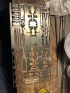
If you go back far enough on this thread you will see I scratchbuilt a nickel silver flexichas chassis for my Gibson F5 and I had formed enough components for a second one (with a view to making it up for the F6). However, in a Zoom call George (Herb Garden of this parish) told me he had recently made up an F5 chassis designed by Peter Stanger of 52F models. As the G5 Peter had designed went together really well I reached out and asked for two, one for the F6 and one for the part built F4/5. Peter even designed in the different footplate thicknesses to cover the brass and whitemetal variants.
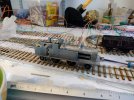
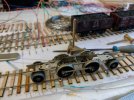
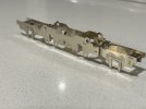
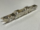
These arrived a few weeks ago and so yesterday I took them out of the box and started work. Some photos are attached.
I have messed up a bit as I thought the carrying wheel horns were to be soldered on to the outside of the frames but, looking further on in the instructions, I see they should go inside so my first job tomorrow evening is to unsolder them and fit them into the right place. A case of measure twice and cut once - not.
Nigel


AJC
Western Thunderer
Nigel.
Shame about your misinterpretation about the horn guides. I always find it somewhat harder to unsolder bits than to fit them in the first place, so good luck.
As a matter of interest, what is the purpose of the large(ish) holes at the top of the frames?
Dave.
Plunger pick-ups?
Adam
James Spooner
Western Thunderer
Dave,Nigel.
Shame about your misinterpretation about the horn guides. I always find it somewhat harder to unsolder bits than to fit them in the first place, so good luck.
As a matter of interest, what is the purpose of the large(ish) holes at the top of the frames?
Dave.
Thanks and you are of course right but it won’t be the first time I have soldered myself down a blind alley. I did it once when I was soldering a Gresley etched brass carriage kit together and soldered the bottom half upside down…
I am reliably informed by m’learned friend Mr Garden that the holes are for plunger pick ups if I want to use them.
Nigel
simond
Western Thunderer
Blowlamp.I always find it somewhat harder to unsolder bits than to fit them in the first place, so good luck.
and good luck…
NHY 581
Western Thunderer
Blowlamp.
Bless you.
AJC
Western Thunderer
Quick question, what temperature solder do you use/recommend for nickel silver please? I'm about to start on a CSP chassis.
Cheers
Tony
Whatever you like! Seriously, I’d use 180 or even multi core for the structure and 145 for detailing and fitting hornblocks if that’s a thing you’re doing. If you’re deft then there’s no reason not to use 145 for the lot.
Adam
76043
Western Thunderer
Thanks Adam, I might be deft, I don't know, but I've always been happy soldering wiring with Maplin multicore and my ancient tin of Fluxite. I did attempt a rigid nickle OO chassis that at least had all the wheels in the same plane with these materials. I want to now try a compensated chassis on this CSP GWR 1361.Whatever you like! Seriously, I’d use 180 or even multi core for the structure and 145 for detailing and fitting hornblocks if that’s a thing you’re doing. If you’re deft then there’s no reason not to use 145 for the lot.
Adam
Just worried sweating coupling rods with multicore might be daft and maybe 145 is better?
I should get my Iain Rice chassis book out again for a read.
Cheers
Tony
James Spooner
Western Thunderer
Tony,Thanks Adam, I might be deft, I don't know, but I've always been happy soldering wiring with Maplin multicore and my ancient tin of Fluxite. I did attempt a rigid nickle OO chassis that at least had all the wheels in the same plane with these materials. I want to now try a compensated chassis on this CSP GWR 1361.
Just worried sweating coupling rods with multicore might be daft and maybe 145 is better?
I should get my Iain Rice chassis book out again for a read.
Cheers
Tony
When the EU rules on lead in solder came out many years ago I invested in a lifetime’s supply of Carr’s 183 degree and 145 degree solder and am slowly working my way through it. Yes, 183 for the big stuff and if I am feeling lazy, for some of the smaller stuff too. I also have a use for Carr’s solder paste and have been known to use that to solder coupling rods together.
Nigel
James Spooner
Western Thunderer
Thanks Rob. Yes, they are rather lovely but from a modelling perspective the issue is that they have a long wheelbase and there are a number of ways of overcoming that. The simplest, I suppose, is to just have two floating pony trucks, but you then have a long loco with a comparatively short wheelbase and a propensity to wiggle. Peter’s approach (and I think the approach adopted on the Rumney models chassis) is to joggle the frames in around the trailing wheels and create a sort of radial truck. It will be interesting to see how that pans out.I'll be very interested in this. I do like a GER 2.4.2T
Rob
Nigel
Herb Garden
Western Thunderer
Dave Holt
Western Thunderer
Yes, I also bought a large reel of 60/40 flux cored solder which I use for most work. For adding additional parts to small items I also use 179 with silver content as well as 145. I try to use the 145 for soldering white metal parts to brass or N/S but for smaller W/M parts O tin the brass or N/S first and use low melt. For all but electrical joints, I use liquid phosphoric acid based flux of 12 or 6%. I'm not the world's most punctilious cleaner of joint edges, but it definitely helps with the low melt.
Dave.
Dave.
James Spooner
Western Thunderer
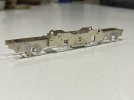
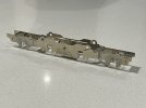
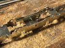
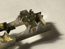
Progress this evening. The horns that I had inadvertently soldered on the outside of the frames have been unglued and refitted inside. The surplus solder was then cleaned off and I moved back into an advance over the previous evening. The compensation beams were soldered up and fitted, as was the ashpan and one of the radial axle assemblies soldered up and tested satisfactorily. Given where I was last night I’m happy with that. Photos attached.
Nigel
Nigel


James Spooner
Western Thunderer
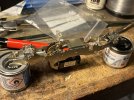
Social activities have got in the way of progress on the chassis recently but this evening I have completed the second radial axle mount and turned my attention to the gearbox. Peter supplied a gearbox with the kit but (my fault for not being clearer) the worm gear has a smaller inside diameter than the shaft on the Mashima 14/20 I planned to use. I had a bit of a rummage around my loco bits and bobs box and dug out a Mashima 14/24 and Branchlines multibox I had planned to use in my D16/3, but was too big. A careful measurement of the F6 drawing shows it will fit quite nicely into the loco if I fit it to the front axle and will also enable me to detail the inside of the cab. What’s more, the assembly fits onto the axleboxes provided by Peter and all I need to do is file back some clearance on one of the frame spacers. If I get sufficient lead into the tanks the whole assembly ought to have quite a bit of grunt! Photo attached of the current state of play.
Nigel
Nigel


