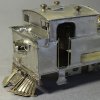
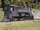
7mm Connoisseur Models LNER N10 Tank Engine

Rob Pulham

Western Thunderer
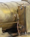
It was at this point that I permanently fitted the boiler in place. Tom Burham had kindly shared some photos of how the brass transition cover was retained by cladding band clamps so I endeavoured to add those. I managed it but I confess that the front one that is fitted to the transition ring is barely visible when you turn it upside down let alone from normal viewing angles.

55388065827_c277642a43_h.jpg

55388999636_4819437ba8_c.jpg

55389184539_d56e442f41_c.jpg

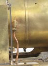
I also fitted the clack valves. I had to make a small top hat type bush to sleeve the pipe as it passes through the foot plate

55388066087_cca9c85aaf_h.jpg

55388999526_468d4259b9_h.jpg

55389400975_b499ce0991_h.jpg

You will also note that I have fitted the filler cap locking screws that I had beefed up in the last post.
 

Rob Pulham

Western Thunderer
I finally got all the cab furniture fitted. I made the individual pieces up last year while out at shows, but I’ve only just got around to fixing them in place.

55389184419_db91163d55_h.jpg

55389132718_5f4a0b5ffa_h.jpg

55389132693_9a2fbab296_h.jpg

55388065912_6a2fd71faa_h.jpg

If you are wondering what the little round bung is on the splasher/locker in the last photo. There was an etched hole presumably so that the reverser could be fitted at that side or it was just a mirror of the splasher on the other side so the hole came with it. Either way, I just turned up a small bung to fill the hole.
 
Last edited:

Arun Sharma

Western Thunderer
I think both versions of the painted slide bars look equally good. Do bear in mind that the outside surfaces of inside slide bars were often painted the same colour as the inside of the frames - mainly red?
Dave.
There was some correspondence a while ago suggesting that the reason the frames on German locos [and the inside of frames and moving parts on UK locos] were painted red was that any cracks would be outlined/filled in with black oil so would be more readily spotted when oiling around by the crew.
 

Rob Pulham

Western Thunderer
The next part on my hit list was the coal rails. Unusually for one of Jim’s kits I had a bit of a fiddle to get it to sit correct and ended up filing the curve to get it to sit better against the rear of the cab.

After looking at the drawing to see how the rails were mounted on the full sized loco, I made up some mounting strips cut from some 10 thou nickel sheet.

55391688713_0f81324a7e_h.jpg

55391951600_c3fc56111c_h.jpg

55390621467_3eb3290688_h.jpg

Then it was the turn of the cab handrails. These are, like on many locos of the period, tapered from the bottom up. I made them by putting some short lengths of 1mm nickel rod into my Dremel laying it flat on the cutting mat and running a diamond file upon it to create a subtle taper. It doesn’t look very tapered in the photos but it does taper from 1mm to 0.7mm over the 30mm or so. I also turned up some washers for the top to take up the difference in the etched holes and some collars for the bottom which gives a bit more area to create the soldered joint while looking prototypical

55395369653_3c1a834c49_h.jpg

55397188923_cf99c95c3c_h.jpg

I have also fitted one of the cab doors. Most photos show one of the cab doors open but the design of the kit doesn’t make that easy, so some more thought is needed before I fit the other one

55397450865_94ba291d0e_h.jpg
 

Dave Holt

Western Thunderer
Rob.
To get the coal space spectacle protection bars a more consistent stand out from the cab back plate. I insert a "U" shaped piece of wire, of the appropriate diameter, horizontally between the bars and the cab plate, and press the bars on to it. Obviously, the width of the "U" has to be less than the length of the shortest bars, so as not to solder it to the job.
Equally, some non-metallic substance could be used.
Dave.
 

Lawrence Boul

Western Thunderer
My approach to tapered handrails is to use tube. In part because the decorative knobs at the top have a spigot that I want to locate into the top of the handrail. But in any case it can be a nice solution as you can run a wire up the tapered tube to form spigots at each end for mounting.

Basically I fit a length of tube into the mini drill chuck with a length of wire within. Taper the tube with emery etc. For 0.1mm wall tube I'm looking to go from nominal dimension at the base to nothing at the top. The resultant piece can then be cleaned up at the top and cut to length. Fitted to the engine with a fresh piece of wire up the middle.

It sounds difficult, but it has been a lot easier than wire for me.

Wa217-300124.jpg
 

Lawrence Boul

Western Thunderer
My approach to tapered handrails is to use tube. In part because the decorative knobs at the top have a spigot that I want to locate into the top of the handrail. But in any case it can be a nice solution as you can run a wire up the tapered tube to form spigots at each end for mounting.

Basically I fit a length of tube into the mini drill chuck with a length of wire within. Taper the tube with emery etc. For 0.1mm wall tube I'm looking to go from nominal dimension at the base to nothing at the top. The resultant piece can then be cleaned up at the top and cut to length. Fitted to the engine with a fresh piece of wire up the middle.

It sounds difficult, but it has been a lot easier than wire for me.

View attachment 268783
It's also possible to cast them in 1 piece as on this F in 1:64.
_HLB5302.jpg
 

Lawrence Boul

Western Thunderer
Rob.
To get the coal space spectacle protection bars a more consistent stand out from the cab back plate. I insert a "U" shaped piece of wire, of the appropriate diameter, horizontally between the bars and the cab plate, and press the bars on to it. Obviously, the width of the "U" has to be less than the length of the shortest bars, so as not to solder it to the job.
Equally, some non-metallic substance could be used.
Dave.
I haven't done it myself, but I've seen card used. Depending on approach, it gets captured, but easy to cut it out especially after heat and flux have attacked it.
 

Rob Pulham

Western Thunderer
Rob.
To get the coal space spectacle protection bars a more consistent stand out from the cab back plate. I insert a "U" shaped piece of wire, of the appropriate diameter, horizontally between the bars and the cab plate, and press the bars on to it. Obviously, the width of the "U" has to be less than the length of the shortest bars, so as not to solder it to the job.
Equally, some non-metallic substance could be used.
Dave.
Thanks Dave,

I have used a U shaped piece of rod in the past, but I find that I use either a thickish strip of scrap etch or a coffee stirrer more frequently. I also tend to fit them in the flat before assembling the cab. - I do need to replace the one that has gone walkabout before I fit the inner window frame. The joys of doing such things while demoing at shows.

I think that there may have a been a little misunderstanding in this case (or perhaps it's me that has read your reply wrong). The fettling I was referring to, is in relation to where the coal rails fit to the curve of the be bunker sides behind the cab.

The rails are full thickness etch and the plating behind is half etched. At each end of the etch where it fits to the rear of the cab, the rails terminate in a curve with the idea being (I think) that you slip the half etch part behind the curved part of the bunkside and the curve of the end of the rails sits into the curve of the bunker side. In this case try as I might I just couldn't get them to sit properly so I ended up cutting away the half etched section and then filing the curve until it sat inside the curve of the bunker side.
 

Rob Pulham

Western Thunderer
I have used tapered nickel silver clock pins from HS Walsh for door handrails but having just looked up the current price I will go back to turning my own from wire!

I have some tapered clock pins (not sure that I got them from HS Walsh though) but the ones I have left, are both too thick and too short for this particular application. I have used them most for taper pins for telescopic axles.
 

Rob Pulham

Western Thunderer
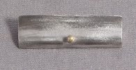
I turned and added knobs to the piano front and smokebox door as well as fitting the locking handles. They are only little things but I perfected a technique where I could knock out a knob in 5 minutes so I made a couple extra for my friend’s G5 at the same time. The locking handles came from the spares box.
55401582488_ddef2f776c_b.jpg

55401582508_72a7133916_h.jpg

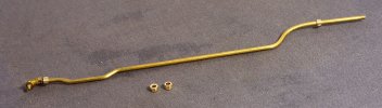
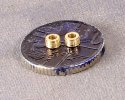
Next on the hit list was the vacuum ejector pipe or rather it was bending it to shape and making and fitting the nuts or slotted retaining rings that were designed to be tightened with a ‘C’ or hook spanner.

I have to confess that it took three attempts to get these to where I was happy with them. For the first attempt, I used a small slitting saw. Unfortunately, it was from a cheap set and the arbour that holds the blades isn’t a very good fit and therefore the blade doesn’t run very concentrically. This combined with trying to cut too many slits for the diameter of the rod basically ended up chewing a third of it away before I gave up.

For the next attempt I kept things simple. I used a couple of pieces of bar with a couple of metric 123 blocks stacked on top of them to get me to the height of the brass bar held in the spin indexer collet. To make the grooves I used an Olfa cutter and reduced the grooves to six from the eight that I had tried on my first attempt.
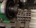
55410975726_1a19b922f5_h.jpg

This worked but I wasn’t happy with the grooves, they were not defined enough. But having got the idea I thought about what I might have that would make a better- defined groove. The next thing that I tried was a carbide 60degree thread cutting tool. Which I lined up on the edge of the 123 block, and by carefully running the point of the tool against the brass rod. After a few passes, the slots were acceptable.
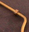
55400041453_948d07d7a3_z.jpg

55398979007_694982ef47_b.jpg

55401442976_2f70477f4d_h.jpg

55401442926_45d4d67255_b.jpg

Here is the finished pipe complete with fittings and bent to shape but not fixed in place yet. I still have the Westinghouse pump and associated pipework to fit in front of the tank which might be easier if I can temporarily remove the vacuum ejector pipe

55403855378_9c2c552660_h.jpg

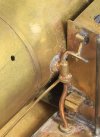
Finally (for now), as I’m returning to the 8F for a bit. Having looked at lot of photos, many of them show, one or both of the tank filler locking screws unclipped and dangling down. There isn’t much room to leave the right hand one dangle due o the Westinghouse pump and governor fitting so I took the left hand one off and refitted it the other way up and slightly bent outwards.
55404122110_5f2357f28e_b.jpg

A small detail but it all adds to the fun.

 

Dave Holt

Western Thunderer
Rob,
Unless you are modelling the loco as static on shed, or have a photo showing one of these running with the lid fasteners undone, I wouldn't model it like that, just for effect. It would be very bad practice to run with the lids unsecured and lead to loss of lots of water during braking.
Dave.
 

Lawrence Boul

Western Thunderer
Simon yes.
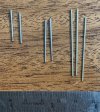
Here are some for comparison. Left, steel, standard taper imperial 1-48 used for fixing telescopic axles
Middle, steel clock pins 1-35
Right, nickel silver taper pins, metric 1-50

View attachment 268839
Handy. A quick look at some drawings for the F class illustrated a few posts ago suggests a base diameter of 1 3/4" tapering to 1" (scaled from the drawing). In 1:64 that's 0.7mm down to 0.4mm over a bit under 14mm - so near enough 1:50.

I see small tapered pins offered online (Universal Tapered Steel Clock Pins) 0.3 - 1.35 over 32 mm (and similar). Cut down that would do me perfectly in S and in 7mm as well. Under GBP10/50, but getting them shipped to NZ is another story.

From a horology forum: "Traditionally, they're made by filing on a wooden block with grooves cut in it. Hold the rod in a pin vice and rotate against the stroke of the file, it's not hard to keep an even finish once you get the knack."
 

Lawrence Boul

Western Thunderer
Unless you are modelling the loco as static on shed, or have a photo showing one of these running with the lid fasteners undone, I wouldn't model it like that, just for effect. It would be very bad practice to run with the lids unsecured and lead to loss of lots of water during braking.
Would it? Most of the engines that I'm interested in don't have fasteners. Certainly the lids are relatively heavy, but if 'lots of water' were surging up I don't suppose they'd resist it. Tanks are baffled, so it's not like the entire volume will be surging. On the other hand, if fastenings are fitted it's presumably because they are necessary.

Not that I have experience or a view - just curious.
 
Top