LNWR Precedent

NickB

Western Thunderer
This is my second G3 loco. I chose it partly because there is plenty of information available. I got copies of the LNWR drawings from the NRM and visited the preserved Hardwicke at Shildon to take lots of photos (great cooperation from the staff at both places). From that I was able to do a very detailed solid model.
I intend to use commercial laser cutting and 3D printing services, and possibly some CNC machining, partly to speed up the project but also because I'm interested to explore how we can use modern manufacturing methods.

Laser cut steel for the frames and other flat components.
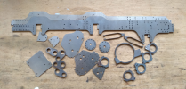
Steel.png

The frames and stretchers were designed with slots and tabs for assembly. The slots were so well cut that I could just put it together for the photo. It will, of course, be soldered up later.
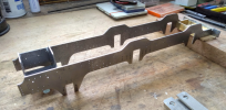
Trial assy.png

I had the driving wheel centres 3D printed in PA-12 nylon some time ago to see if the combination of printed centre and turned steel tyre was viable.
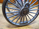
Driving wheel.png

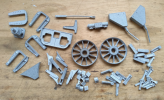
Other components 3D printed.

PA12.png

There is also a growing collection of machined parts. These were the ones I judged not feasible or too expensive to have made.
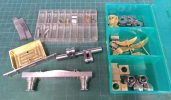
Machined parts.png

And this is my bevel gear drivetrain. It comprises a Polulu 60W motor which comes with an integrated gearbox to drop the rotational speed to 500 RPM, then a bevel gear to the driving axle. It is a nice compact package that fits between the driving axles. The problem with bevel gears (as I discovered) is the axial force they exert - they try to push each other out of mesh. Not only was it hard to stop the driving gear sliding along the motor shaft, but I was concerned about durability because, when I dismantled the inline gearbox, I discovered that the thrust bearing was quite crude (but at least it had one).

To allow for this I added a ball thrust bearing between the bevel gear and the motor casing to take the load. There wasn't enough room on the driving axle for anything similar to that, so I added a brass sleeve to fit between the spur gear and the gearbox frame. At least that will be quite accessible for regular oiling.
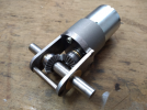
Powertrain.png

Nick
 

Ian_T

Western Thunderer
Very interesting Nick - and excellent work too!

Look foreward to further updates.

Regards,

IanT
 

NickB

Western Thunderer
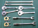
Coupling, connecting and eccentric rods made by traditional drilling, sawing and milling.

Rods.png

While making them, it occurred to me that I could have shortened the process.

When I was deciding what to make by laser cutting, I was concentrating on flat parts like frames, and the rods struck me as too 3D. Not so! The traditional way of making them is to start by cutting the outline and then machining the width as necessary. Since laser cutting can be done in a wide range of material thicknesses, I could have had the outlines (side or top, depending on the complexity of the part) done that way, leaving me with the 3D shaping to do on my mill. That would have been a significant saving in time. Oh well, I'll remember that for the next project.

Next up, the remainder of the valve gear parts, then assembly can start.

Nick
 

adrian

Flying Squad
When I was deciding what to make by laser cutting, I was concentrating on flat parts like frames, and the rods struck me as too 3D. Not so! The traditional way of making them is to start by cutting the outline and then machining the width as necessary. Since laser cutting can be done in a wide range of material thicknesses
Interesting to see what the new processes can be used for. I know for general fabrication work then water jet cutting for thicker steel plate is used frequently. This doesn't give the fine detail for modelling so I'm curious what sort of thicknesses you'd consider with the laser cutting.
 

NickB

Western Thunderer
Adrian,

The company that I use (fractory.com) will laser cut mild steel in thicknesses between 0.8 and 20 mm. They also do water jet cutting up to 100 mm. Those aren't hard limits for the processes because it depends on the equipment available, but looking at other companies that will handle small orders, the thickness ranges appear to be typical. For what I need, I can't imagine requiring thicknesses above 10 mm, and most parts are a lot thinner than that. I've no direct experience of water jet cutting so I can't comment on the relative detail that can be obtained.

Nick
 

Mike W

Western Thunderer
I have seen waterjet cutting but always use laserjet. Laser is more common and cheaper. Water gives a better finish on the edge but also has more draw, so the cut is tapered and that is more noticeable on thicker material. For my purposes the finish on the edge of a laser cut steel part is quite good enough, especially if the machine is properly serviced and calibrated.

Mike
 

NickB

Western Thunderer
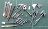
Here are the slidebars, crossheads and all the remaining valve gear parts, all made by traditional methods. As previously mentioned, I'll consider making more use of laser cutting next time around, but sadly not 3D printing, which in metal is way outside my budget.

IMG_20221116_142709635.jpg

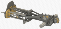
When assembled, it should look like this. The valve gear is a form of Stephenson's, but straight link and balanced, so the valve rod goes up when the link goes down (and vice versa). From the modelling point of view, it just means more components and pivots (groan).

Loco v104.png

That's everything done for the chassis, bar a few little bits and pieces. Ready to start building!

Nick
 

NickB

Western Thunderer
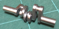
The crank axle.

Crank axle.png

In case anyone is in doubt, it is built up, not machined from solid - I'm not clever enough to do that. All the joints were glued and pinned, then the axle was cut away between the cranks and cleaned up. The eccentrics are secured with grub screws so as to get the valve timing right. I know it's an electric drive, but I might as well get it right.

When I checked my photos of the preserved Hardwicke, I was surprised to discover that the left crank was leading. On delving further, I discovered that this was common practice for the LNWR, unlike many other British railways and builders where the right crank led. That meant I've built several locos in smaller scales the wrong way round. Whew, nobody noticed (unless they were too polite to mention it).

Nick
 

NickB

Western Thunderer
"There's this crazy guy in G3 who assembles his model locos the same way as the real ones were ..."

Cylinder front 1.png

Let me explain. Usually I'd do features like this using simulated studs and nuts, but my usual suppliers could not provide them in the right size. Why not, I thought, use scale nuts and bolts? M1.0 was exactly right, and I bought enough of them from Prime Miniatures for less than I would have paid for the simulated fittings. Win, win! Okay, they were a little more fiddly, but the result was worth it.

Cylinder front 2.png

Nick
 

victorianman

Western Thunderer
Great work. The late Geoff Pember also ran into the left crank lead problem when he built a Precedent in 7mm many tears ago. I think the article is in an early 'Model Railways' mag.
 

Mike W

Western Thunderer
You are dead right victorianman - I remember that too! Geoff I thnk couldn't live with the error and made a new axle. Think if it was me I'd just keep quiet about it.

Mike
 

NickB

Western Thunderer
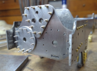
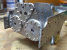
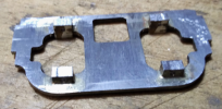
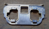
This project was always an experiment into how far I could take new technologies, and of course you don't know the limits until you try to push too far. Herewith, the story of the motion plate. The real thing wasn't a plate, it was a cast component with flanges, strengthening ribs, and of course brackets to hold the slidebars. An obvious candidate for 3DP.

Motion plate 3DP.png

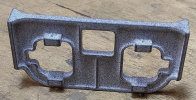
Unfortunately the print in nylon wasn't up to the job. It was just too flexible. Mike Palmer very kindly offered to make one in brass on his CNC mill, but the many narrow corners and pathways would have been a serious struggle. Miniature CNC machines do exist, but they come with anything but miniature price tags. So it was back to the old ways, starting with a steel plate (done by laser cutting, FWIW). To this I silver soldered the brackets for the slidebars.

Motion plate steel.png

The tedious bit was cutting out the ribs along the top and round the openings from brass with a piercing saw, then soft soldering them into position. You will see I have simplified the detail somewhat, but I don't think it will be too obvious. The plate will be attached to the frames using tabs and slots instead of rivetted flanges. The flanges on the original will be dummies, riveted to the frames.

Motion plate overlaid.png

How else could I do it? 3DP in metal would be nice, but brass has become very expensive and for various reasons mild steel still isn't very printable. Stainless steel is probably the best option at present (as long as you can be sure you will never need to solder anything to it), but for this component it is still about £40 for a one-off. No, until metal printing becomes a lot cheaper and better, for some things the old methods will still be used.

Nick
 

Osgood

Western Thunderer
What wonderful engineering!
I imagine laser cutting has made EDM by wire an almost obsolete process, since a laser can go wherever a wire can go?
 

simond

Western Thunderer
Certainly our local mould makers are still using wire cutting and electro-erosion die sinking.

now, if I could 3DP the carbons…
 

Osgood

Western Thunderer
Certainly our local mould makers are still using wire cutting and electro-erosion die sinking.

now, if I could 3DP the carbons
Ah that's the phrase I was searching for! The one thing I guess lasers cannot do - accurate machining of blind holes / recesses?
 
Top