LNWR Precedent

Osgood

Western Thunderer
...

View attachment 169458

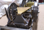
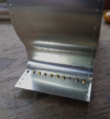
The frames and stretchers were designed with slots and tabs for assembly. The slots were so well cut that I could just put it together for the photo. It will, of course, be soldered up later.

View attachment 169459
Catching up here and going back to post 1 - a quick question re. production drawings of laser-cut components:

Do you have to specify the exact dimensions and tolerances for such tab / slot joints, or can you just draw at nominal size and specify whether interference or clearance, thereby leaving the company to fine tune the (I assume DXF?) laser manufacturing files?

Thanks.
 

NickB

Western Thunderer
Tony,

The laser cutting process is very accurate, so you only have to give the slots and tabs identical dimensions. Occasionally I find a little bit left in a slot, but it is only a moment's work with a needle file to clear it. The result is not an interference fit that can be relied on to stay in place, the parts must be soldered, but I find that the tabs and slots are good enough to guarantee alignments.

Nick
 

Mike W

Western Thunderer
Tony,
.dxf is preferred usually. Allow no tolerance - not like etching. The width of the cut is set in the machine, it knows which is the part and which the scrap, so offsets itself accordingly. There is a slight draw (i.e. the cut is angled) but very little and far less than with water-jet cutting. A single dimension line can be useful as a sanity check if you've not used that firm before, but they won't read any other dimensions.
Mike
 

Jon Nazareth

Western Thunderer
Nick
It seems to me that you are working from a decent set of drawings. Do they show the detail of fixing the guard irons to the frames i.e., bolts or rivets and what size?

Jon
 

NickB

Western Thunderer
Jon,

My principal resource is the GA drawing. It distinguishes bolts from rivets but does not give sizes. The drawing is large enough to scale sizes but of course there is no guarantee about accuracy. I also have some detail drawings where I was able to find them at the NRM, though nowhere near a complete set. The Bill Finch portfolio from the LNWR Society has dimensioned sketches of many fittings. I also have photographs that I took of the preserved Hardwicke which are helpful in understanding the drawings and confirming dimensions. There are still a few puzzles but I'm confident that I have most of the model right, or as near right as I'm capable of making it.

Nick
 

NickB

Western Thunderer
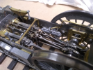
The ash hopper under the smokebox is fairly unique to LNWR locos as far as I know. Photos don't make it clear, but by peering underneath the preserved Hardwicke I managed to make out what it looked like, and I think this is a fair representation. The cylinder drain cocks were based on commercial handrail knobs, since they were a spherical shape and about the right size. It saved me a tricky machining job.

Chassis 1.png

The last details are the drain cock linkage, the pipe to the crosshead pump, and the oilers to the leading wheel axleboxes. And that completes the model below the footplate (I think). Next up will be the smokebox.

Chassis 2.png

Nick
 

NickB

Western Thunderer
Different companies (and probably different draughtsmen within them) had different ideas about how much information to put on a GA. I've spent a lot of time trying to measure dimensions off photographs of the Precedent!

Nick
 

bambuko

Western Thunderer
It actually states that the bolt size for connecting the guard irons should be 7/8" which is about 14BA,
That's the size of the thread, but it tells you nothing about the bolt hexagon head size...
which I guess is far more important from the point of view of model appearance,
hence wide availability of BA bolts with one size smaller hex
None of the GA drawings I have include this kind of info
 

Jon Nazareth

Western Thunderer
Nick
I've done the same with GA drawings trying to establish nut and bolt head sizes, very frustrating.

Bambuko
When I used to dabble in model engineering, I always used to chose a size smaller fixing and it does make a difference to the look of the finished model. Prompted by your reply, I did look up my supplier and the smallest he does is 10BA with a size smaller head, heigh ho.

Jon
 

NickB

Western Thunderer
Some more experiments with colour. I realised that the base colour might make a difference, so on the LHS of this test piece I first painted an opaque layer of yellow then covered it with out-of-the-tin "brass" paint. It's about the same shade as the sample of brass and yellow mixed, but with a bit more metallic lustre.

Following up the suggestions here to try gold paint, that is what you can see on the RHS. It's not very brassy, and not very gold either for that matter. I also tried a sample on a plain white background to see if it made a difference, but not really.

So I still haven't found a way to make plastic look like brass.

Nick

Brass painting 2.png
 

Jon Nazareth

Western Thunderer
Nick
If you pop along to a decent art suppliers, you will find gold powder in different shades of 'gold'. This can be mixed with a medium, clear laquer/varnish, and painted on. I've used it in the past and it has worked for me. I tend to use 'gold size' as it's what I have o the shelf.

Jon
 

Jon Nazareth

Western Thunderer
Nick
Forgot to say that the powders are ground metals but not sure which sort or how the colour is changed.

Jon
 

NickB

Western Thunderer
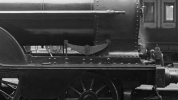
Back to the loco. Most electrically powered locos, as far as I know, are built using a separate chassis and body, the body removing to get at the works. That's not going to work here because of the way the leading wheel spring is attached. The hangers are bolted to the frames to take the load, but the front hanger has to pierce the smokebox wrapper.
Smokebox assembly problem.png

That means if you bolt the hangers to the frames, you can't get the smokebox off, but with the smokebox and boiler in place it is all but impossible to remove the spring. Incidentaly, on the real thing lead sheet was forced into the space between the hanger and the wrapper to preserve the smokebox vacuum. It all sounds like a bit of a bodge. Couldn't they come up with a better idea? Clearly, DFMA (Design for Manufacture and Assembly) hadn't been invented in Victorian times.

My answer is to attach the smokebox permanently to the frames. The boiler is part of the body assembly, and bayonets into the back of the smokebox. To remove the body, release the screws which will be under the cab, slide the body backwards about a millimetre, and lift it off vertically. It will work because there are only two external pipes connecting the boiler and the smokebox and it's easy enough to release them for dismantling.

The smokebox skeleton is a straight forward bit of sawing, filing, and turning.
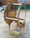
Smokebox skeleton.png

Thw wrapper has two rows of rivets at front and rear. I decided to press them rather than add them separately and solder them, partly because I couldn't find any rivets of the right size, but mainly because I didn't fancy drilling so many tiny holes.

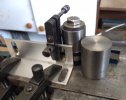
When I made my rivetting tool, many years ago, I designed it so that it could be clamped to the bed of my Sherline lathe. The work is clamped to the cross slide and moving the saddle and cross slide gives nice uniform rows of rivets in both directions. Here is the first row
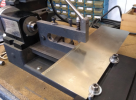
Smokebox riveting 1.png

and here is the second row, positioned by cranking the x-axis the correct amount and maintaining the same spacing on the cross slide.
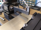
Smokebox riveting 2.png

I prefer doing it that way than relying on the anvil diameter to space the rivets. It works better for me but I know that the late, great Beeson and Reynalds both used the anvil edges, and who am I to argue?

Nick
 

NickB

Western Thunderer
Thank you, Jon. I can set the spacing using the anvil diameter and an adjustable fence in the other direction, and if there are only a few rivets I do it that way. But if I have a line of 50 rivets to do I like to minimise the chances of the 49th somehow going out of line.

Nick
 

NickB

Western Thunderer
I hope no-one is expecting an easy way to form the reverse curves in the wrapper so that it fits the skeleton, because I'm going to disappoint you. I used rolling bars and bending bars, did it a bit at a time, kept trying it against the skeleton - and it still didn't fit perfectly. But I managed to persuade it into place by holding it on the skeleton with a collection of clamps before soldering it up. It was not perfect but the solder fills up any remaining gaps.

But before that, it was necessary to add the dummy boltheads at the lower edge of the wrapper. The missing one is where the spring hanger will go.

Smokebox wrapper.png

I cut the wrapper slightly over width so that I had an edge on the outside to solder to (much easier than soldering inside), then filed it back flush to give nice sharp corners.

Smokebox front.png

Smokebox rear.png

The black bits are 3D prints of the chimney, door, and the blower pipe elbow in SLS nylon. I had them done in black rather than the default white so that if anything got scratched it would not show badly. Unfortunately it makes it difficult to photograph to show the detail to advantage, but take my word for it that the surface finish and the detail are excellent. I was particularly impressed by the consistently thin base of the chimney (it used to take me several hours to file these up in brass and I never got it that consistent) and the detail of the door wheel and handle.

These prints are a step up from the last set of comparable prints that I had done a couple of years ago. It just shows how quickly 3D printing technology continues to evolve.

Nick
 

NickB

Western Thunderer
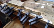
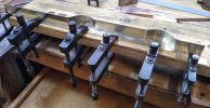
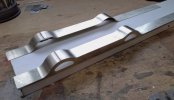
Next up, the footplates. Yes, there are two of them, LH and RH. Oh dear, more curves to form where the tops go up and over the coupling rods. After an abortive attempt to make them in one piece, I decided to make them in three pieces and join them. Here is a reverse curve being formed around suitable blocks (diameter chosen by experiment on pieces of scrap).

Footplate_1.jpg

Then soldered to the footplate side.

Footplate_2.jpg

You can never have too many clamps.

Footplate_3.jpg

All done and cleaned up. Unlike Ernie Wise's hairpiece, you can see the joins (just) but they will disappear under a coat of paint.

Footplate_4.jpg

When I encounter things like this I always wonder how it was done on the prototype. Did they somehow shape it all in one piece, or make it in sections? There is no evidence of joins in any of the photos that I have. I'll have to examine Hardwicke again next time I get the chance of a visit to Shildon.

Nick
 
Top