You are using an out of date browser. It may not display this or other websites correctly.
You should upgrade or use an alternative browser.
You should upgrade or use an alternative browser.
The Heybridge Railway, 1889 to 1913
- Thread starter Richard Gawler
- Start date
Threadmarks
View all 83 threadmarks
Reader mode
Reader mode
Recent threadmarks
GER 10 ton van (1910) - buffers and completion Rebalancing the Wagon Fleet New Standards for Building Plain Track New Sleeper-built buffer stop (1) construction New Yard crane New Water column New Sleeper-built buffer stop (2) finishing New Ballast - geology and sources NewRichard Gawler
Western Thunderer
Perfect.Unsoldering is much easier with a blowlamp. Chef’s style is ideal, as they usually have s piezo igniter, and are adequately big for 7, and probably 10, mm scale unsoldering.
I have discovered, I can have a good fit between the deck and the side girder, or between the deck and the curb rail (kerb rail?), but not both.
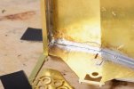
End of side girder detached using blowlamp.
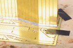
Curb rail fits neatly. I left the curb rail on its fret for assembly (as explained in the kit instructions), this makes getting a right angle onto the deck straightforward.
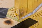
I let the flame linger too long on the joint below this half-etched area, which responded by pinging up into an arc shape.
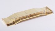
I have now deviated from the kit instructions to add the six gusset brackets along the first side. Time will tell whether this was sensible, but I have now made up one solid side and the whole assembly can still sit flat upside-down.
I am posting these photos, not simply for the folk here who are helping me so much, but also hoping that someone who has never built a brass kit (and this was me two months ago) will find them useful. Perhaps they can bridge some of the gap between the magazine articles aimed at beginners (static grass and ballasting especially!) and the accounts of building large and high-end loco kits.
My plan now is to add the second curb rail before the second side girder - because I can file down the girder to make it fit the deck but the etched groove for the deck in the back of the curb rail is a fixed and unchangeable thing.
Last edited:
Richard Gawler
Western Thunderer
I am studyingTo be pedantic, the 8'6" wheelbase Jubilee wagons were only ever built with sprung buffers. The dumb buffer version from 1886 had a 7'6" wheelbase and were a foot shorter. All of the difference in length is in the side doors so chopping 7mm out of the centre of the sides produces a very accurate model, see one I did earlier here #23 (if the link works).
Tatlow P, "An Illustrated History of LNER Wagons - Volume 3 LNER Scottish Area" Didcot 2009 (Wild Swan)
especially figures 5 and 6, which show the older and later Jubilee wagons.
It seems to me,
Earlier wagons were 17 ft 9 in over buffers and 7 ft 6 in wheelbase (fig.5)
Later wagons were 18 ft 3 in over buffers and 8 ft 6 in wheelbase (fig.6)
Yes the extra length of the body in later wagons is in the width of the side doors, so I would need to remove 3.5 mm from both doors, and remove 7 mm from the solebars between the wheels. For a dumb-buffered wagon it would then be easy to then extend the shortened solebars by a comensurate amount to create the 17ft 9 in length. For a sprung-buffered wagon there would be quite short pieces of solebar to cut the fill the gaps behind the headstocks.
Overseer
Western Thunderer
The North British Railway General Arrangement drawing (Dg. No. 130Wb) dated 1886 shows the length over the dumb buffers as 17ft 0in and 7ft 6in wheelbase. The body is 13ft 10.5in internal plus 3 inch planks at fixed end and 5 inches at the door end for the planks and external braces. The side door is 3ft 4in wide. The 17ft 9in overall length dimension may be a typo by Tatlow, it should be 17ft.I am studying
Tatlow P, "An Illustrated History of LNER Wagons - Volume 3 LNER Scottish Area" Didcot 2009 (Wild Swan)
especially figures 5 and 6, which show the older and later Jubilee wagons.
It seems to me,
Earlier wagons were 17 ft 9 in over buffers and 7 ft 6 in wheelbase (fig.5)
Later wagons were 18 ft 3 in over buffers and 8 ft 6 in wheelbase (fig.6)
Yes the extra length of the body in later wagons is in the width of the side doors, so I would need to remove 3.5 mm from both doors, and remove 7 mm from the solebars between the wheels. For a dumb-buffered wagon it would then be easy to then extend the shortened solebars by a comensurate amount to create the 17ft 9 in length. For a sprung-buffered wagon there would be quite short pieces of solebar to cut the fill the gaps behind the headstocks.
Not sure what you mean by removing 3.5mm from both doors, there is only one side door on each side. The conversion of the Parkside kit just needs 7mm taken out of the side doors and 7mm from the centre of the solebars. The 7ft 6in wheelbase wagons came in dumb buffer and sprung buffer versions so there is a choice of whether to make dumb buffers or fit the kit buffers.
Richard Gawler
Western Thunderer
Thanks for thisThe North British Railway General Arrangement drawing (Dg. No. 130Wb) dated 1886 shows the length over the dumb buffers as 17ft 0in and 7ft 6in wheelbase. The body is 13ft 10.5in internal plus 3 inch planks at fixed end and 5 inches at the door end for the planks and external braces. The side door is 3ft 4in wide. The 17ft 9in overall length dimension may be a typo by Tatlow, it should be 17ft.
Not sure what you mean by removing 3.5mm from both doors, there is only one side door on each side. The conversion of the Parkside kit just needs 7mm taken out of the side doors and 7mm from the centre of the solebars. The 7ft 6in wheelbase wagons came in dumb buffer and sprung buffer versions so there is a choice of whether to make dumb buffers or fit the kit buffers.

Sorry I was counting the side doors, one on each side, as two doors but I am sure it's easier to just think in terms of altering one side and then working up the other side to match.
On my Parkside mouldings, the side door measures 27.5 mm wide representing 3 ft 11 in. So if I removed 3.5 mm from the middle of the door, this would give me a 24 mm wide door representing 3 ft 5 in. Doing this, the internal length of the body would reduce to 96.5 mm representing 13 ft 9 in. So, taking off 3.5 mm gives a door a scale inch too wide and a body a scale inch too short and I would be most happy with the appearance achieved by doing this. This leaves me to take 7 mm off the solebar (somewhere near the middle to preserve the moulded ironwork) to make the 7 ft 6 in wheelbase, and then extend the ends of the solebar to suit the chosen buffers.
Perhaps I should scan Tatlow's drawing (his figure 5) and send it across in a PM? It might have some anomalies compared to the GA, and I don't have sight of the GA.
Overseer
Western Thunderer
Apologies, you are right. It is about 3.5mm which needs to be removed from the centre of the body, and that is what I did. I should have checked before the previous post. I made new solebars instead of cutting up and extending the ends of the kit ones, it seemed simpler. I should really finish mine.

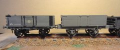
I have also attached a pdf of the GA which may be helpful.


I have also attached a pdf of the GA which may be helpful.
Attachments
Richard Gawler
Western Thunderer
I was beginning to cheer up thinking I wasn't the only person with chronic insomnia but now I realise you are already well into this afternoon.
Your models are lovely, I think I must have another go. Changing the brake lever for something narrower seems to lift the whole model.
Your models are lovely, I think I must have another go. Changing the brake lever for something narrower seems to lift the whole model.
Richard Gawler
Western Thunderer
I have returned to my Hydra.
I have found this kit rather harder to build than the apparently similar Lomac-L from the same manufacturer because the angles for the deck set out on the top edges of the frames do not match up with the grooves for the deck etched into the curb rails.
Trying to compensate for too many things at the same time and using an awful lot of solder in the process I had ended up with a gentle lateral curve along the length of the first frame. The offset was about 1 mm so not enough to notice with the model on the layout but really annoying when looking underneath. I ended up taking the torch to all the gusset plates and the frames and rebuilding them.
Happy again I continued to ignore the sequence of assembly suggested in the instructions and added as many brass detail parts as I could.
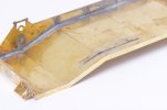
This photo shows the re-worked frame. At least the parts were pre-tinned. The second curb rail went on easily.
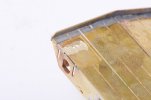
The half-etched areas above the buffer locations had bulged upwards under the heat of the torch so I ground these down a bit.
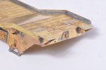
I now had enough space to let the plates for vehicle wheels to sit flat. The support brackets for these went on next and so did the reinforcing plates for the couplers.
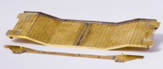
Now I really had to add the second side frame.
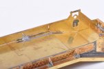
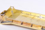
The error is a gap of most of 0.5 mm along the frame/deck joint except at the two ends of the frame. It seemed sensible to tack the frame at the centre and work outwards so I soldered on a strip of fret to give myself a foundation to work from.
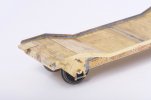
And then, well I just added the wheels in their bearings. This was so easy, yet I had been anxious about these since I started. There is loads of space to manoeuvre the wheels and their bearings, and the model sat flat on the track at the first attempt.
This stage always seems like a threshold to me, it is the moment when a build goes from being an assembly of parts which still might get consigned to the bin, to the essence of a model railway wagon. I soldered the second side frame up solid (with more scrap fret to save solder), and the model is now "a wagon".
I have found this kit rather harder to build than the apparently similar Lomac-L from the same manufacturer because the angles for the deck set out on the top edges of the frames do not match up with the grooves for the deck etched into the curb rails.
Trying to compensate for too many things at the same time and using an awful lot of solder in the process I had ended up with a gentle lateral curve along the length of the first frame. The offset was about 1 mm so not enough to notice with the model on the layout but really annoying when looking underneath. I ended up taking the torch to all the gusset plates and the frames and rebuilding them.
Happy again I continued to ignore the sequence of assembly suggested in the instructions and added as many brass detail parts as I could.

This photo shows the re-worked frame. At least the parts were pre-tinned. The second curb rail went on easily.

The half-etched areas above the buffer locations had bulged upwards under the heat of the torch so I ground these down a bit.

I now had enough space to let the plates for vehicle wheels to sit flat. The support brackets for these went on next and so did the reinforcing plates for the couplers.

Now I really had to add the second side frame.


The error is a gap of most of 0.5 mm along the frame/deck joint except at the two ends of the frame. It seemed sensible to tack the frame at the centre and work outwards so I soldered on a strip of fret to give myself a foundation to work from.

And then, well I just added the wheels in their bearings. This was so easy, yet I had been anxious about these since I started. There is loads of space to manoeuvre the wheels and their bearings, and the model sat flat on the track at the first attempt.
This stage always seems like a threshold to me, it is the moment when a build goes from being an assembly of parts which still might get consigned to the bin, to the essence of a model railway wagon. I soldered the second side frame up solid (with more scrap fret to save solder), and the model is now "a wagon".
Last edited:
Richard Gawler
Western Thunderer
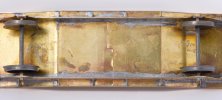
I have ended up with the axles parallel but both are twisted a little counterclockwise.
I will make a guess, this is because both frames are identical but they have their axle holes offset a fraction of a millimetre and this error doubles during assembly. Certainly, both frames are tucked snugly against the insides of the headstocks and I didn't adjust them to do this. The wagon runs sweetly with no 'rock'.
My gut feeling is to leave things alone. I could take out two wheel bearings and elongate their holes sideways but I suspect this will make things 'different' but not necessarily 'better'.
Please, does this sound ok? I can watch out for this on the next build where the axle holes are a part of the frames and not in separately-fitted axleguards.
simond
Western Thunderer
you might get away with it, but, you might also find that it hurls itself into the ballast at every opportunity, those being fishplate joints where the track is going to the left, if I read your photo correctly, and points, where it may choose to find the gap between closed blade and stock rail.
The flanges will be pressed to the rail on one side, and if that side is leading, and there is something to climb, it may misbehave.
if you can, my suggestion would be to fit at least coupling hooks and to take it in current state to a test track and run it both ways to see if it does have ballast-seeking properties. If not, perhaps leave it.
A piece of something fairly hard, half an inch thick, 6 inches long, and wide enough to be a snug fit between the wheel backs, is a useful addition to the armoury.
Rob Pulham
Western Thunderer
These Brassmasters Axle spacing jigs are really useful too - available in 4mm and 7mm scales.
Richard Gawler
Western Thunderer
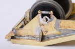
I need more confidence, it was straightforward enough to take out the wheels and open up the holes for the bearings.
I have shuffled the bearings along on opposite corners. The axles are still parallel in both planes . . . the model now looks better and squeals a bit less on curves.
My test track is a Peco Setrack L/H point with a Setrack curve connected on the diverging leg to make a reverse curve, plus lengths of Streamline attached to give me a total run of 7 feet plus a siding. I think I am fortunate to have already built the Lomac-L and seen it run fine on my test track and on the club track. Because, the Lomac and the Hydra share a 130 mm wheelbase. If I hadn't built the Lomac I would be saying "the Hydra is bound to squeal a bit on the curves because of its long fixed wheelbase". Well, the Hydra is now squealing less, but the check rails are certainly doing their job on my point.
I want to think, the Lomac runs better on tight curves because it has smaller wheels, but really this is conjecture. I will take the Hydra to West Bergholt on Saturday, it will be able to run much faster on the club track and I can see how it behaves on gentler curves before I add the cast axleboxes.
Richard Gawler
Western Thunderer
A piece of something fairly hard, half an inch thick, 6 inches long, and wide enough to be a snug fit between the wheel backs, is a useful addition to the armoury.
These Brassmasters Axle spacing jigs are really useful too - available in 4mm and 7mm scales.
I had some fine thoughts of setting up the brake blocks a hair's breadth away from the wheels (Slater's) but the wheels 'wobble' when they rotate - not really concentric or orthogonal to their axles. So while I like the idea of a lump of hardwood or similar, the Brassmasters jig is probably the better way to go for me. Perhaps, because nearly all of my wagons will be a 7' 6" or 9" wheelbase, I could make some kind of a jig. Some U-shaped brass to slip over the axles, and longitudinals of FB rail to connect them together.
Last edited:
Richard Gawler
Western Thunderer
A small question while I am waiting for Saturday to come . . .
Please, why do we put springs on coupling hooks in 7mm scale? It seems to me, on a lightweight train they do nothing and on a heavy train we would be better off with a length of brass wire soldered in to tie the two hooks together.
Please, why do we put springs on coupling hooks in 7mm scale? It seems to me, on a lightweight train they do nothing and on a heavy train we would be better off with a length of brass wire soldered in to tie the two hooks together.
simond
Western Thunderer
Habit?
Convenience?
Reduction of shock loading?
Buffers not to scale (too long)?
Couplings not to scale (too short)?
Old eyes?
Shaky hands?
(List edited to include) Smaller than scale radius curves
Strong springs are ok, the weak and wimpish springs supplied on many RTR models are worse than useless, and can be rectified by the application of a drop of epoxy.
it’s easy to replace the springs on couplers with a tail-with-holes with a bit of rubber tube, to give some “shock absorption” and on brass kits, you can always solder the hook to the buffer beam.
btw, redundant coupler springs from Premier couplings are perfect for floating pickups.
Last edited:
Richard Gawler
Western Thunderer
My favourite installation so far is on my Lomac-L, where there is a piece of piano wire across the backs of the buffer stems and through the shank of the coupler. This would be perfect, except putting quite thin wire to give a lovely soft compression on the buffer heads leaves the coupler too wishy-washy. I might solder up the couplers and keep the nice buffers.
Last edited:
Richard Gawler
Western Thunderer
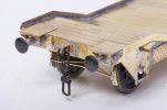
The links for the screw couplings are two loops of brass etch fixed onto a whitemetal casting in the middle. I tried to make these articulated by riveting the spigots on the casting over the holes in the brass loops but everything seemed a bit fragile so I soldered them up solid. The result is a solid coupling bar, this seems to "work" but of course it looks a bit odd when propelling the train. It will probably be fine for me because the adjacent wagons will have three-links and I can use these to couple up the wagon. Colouring is Carr's metal blacking for brass (this makes the white metal part go a bit green but not unrealistically so) and then the black Sharpie.
The buffers are Peco/Parkside heads from my Jubilee wagon kit on the Connoisseur bases. I made the heads sprung but the springs creep up the buffer shanks into the space behind the heads and this leaves the heads slack and drooping and with hardly any sprung travel. Wanting Simplicity and getting a bit weary, I Araldited them solid.
The model is now needing only its axle guards and brake pipes and these can come after its test run, hopefully at reasonably high speeds over pointwork.
Last edited:
Richard Gawler
Western Thunderer
The model is now needing only its axle guards and brake pipes and these can come after its test run, hopefully at reasonably high speeds over pointwork.
I have devised a simple test for track-worthiness: arrange nine or so loose-coupled wagons as a train, and propel this flat out around the club track. Two laps clockwise, two anti-clockwise. A wagon is deemed to have passed if it stays on the track throughout. This involves passing eight facing points and eight trailing points in total.
The effectiveness of the test is limited by the motive power, in this case my Minerva K class at its maximum speed, and by the state of the club track, which is pretty good; but the Hydra and seven other wagons stayed on the track throughout. The 'Jubilee' wagon (described a few posts ago) came off the rails on lap number 3 but managed laps 1, 2 and 4.
I think, the Hydra is good enough to receive its remaining detail parts and paint.
Richard Gawler
Western Thunderer
I agree entirely but I didn't have the presence of mind to do this and the next club meeting is in September.
I think my best bet is use a reverse curve constructed from a Setrack point and a Setrack curve, and to pass the wagon through this by hand. I can hear and feel the flanges scraping their way along (3' 7" wheels on the Hydra) so I reckon, if the standard of running feels consistent in all four permutations of travel, the wagon is running as well as I can make it.
The use of a rigid 130mm wheelbase on such tight curves is quite unpleasant, but my GER/LNER Lomac runs more sweetly here. I'd like to attribute this to its smaller (2' 9") wheels.
Threadmarks
View all 83 threadmarks
Reader mode
Reader mode
