Nick Dunhill
Western Thunderer
The cylinder blocks were a doddle to fit. They just needed a smidge off the sacrificial layers round the sides. The slide bar castings from Laurie Griffin needed a fair bit of fettling and a lot of straightening and realignment. A bit of patience paid off though. I also made the connecting rods supplied as etches from Mick D.


The 3D printed cylinder block is pinned in place with brass rods, and glued to the frame with epoxy.
The crank castings needed a fair bit of fettling and straightening too. Maybe it's time for some new moulds for the waxes?
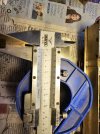
The crank axle was held in position in the photo shown below. The crankpins on the wheels fall on the points of the square bosses on the axle ends. This means that the crank casting could be carefully measured and positioned for soldering. Usually the crank webs are an interference fit on the axle and will be a push fit for soldering. These were a sliding fit so needed some clamping.

The crank castings were soldered one at a time, and then the axle cut and loads of cleaning up carried out. I use electrical solder and Baker's flux.


The anchor points for the anchor rod were fixed to the lower slidebars, as were oil pots to the uppers. The rest of the day was taken up with making valve gear rods from the etches Mick produced.


The valve gear comprises etched parts and Laurie Griffin castings. I don't hold out much hope for the castings, as they are a generic set and I have concerns that they won't mate with the etched parts copied from the GA. We will see, when work recommences on monday!
The 3D printed cylinder block is pinned in place with brass rods, and glued to the frame with epoxy.
The crank castings needed a fair bit of fettling and straightening too. Maybe it's time for some new moulds for the waxes?
The crank axle was held in position in the photo shown below. The crankpins on the wheels fall on the points of the square bosses on the axle ends. This means that the crank casting could be carefully measured and positioned for soldering. Usually the crank webs are an interference fit on the axle and will be a push fit for soldering. These were a sliding fit so needed some clamping.
The crank castings were soldered one at a time, and then the axle cut and loads of cleaning up carried out. I use electrical solder and Baker's flux.
The anchor points for the anchor rod were fixed to the lower slidebars, as were oil pots to the uppers. The rest of the day was taken up with making valve gear rods from the etches Mick produced.
The valve gear comprises etched parts and Laurie Griffin castings. I don't hold out much hope for the castings, as they are a generic set and I have concerns that they won't mate with the etched parts copied from the GA. We will see, when work recommences on monday!