Michael's Werkbank (Bavarian PT2/3)

Yorkshire Dave

Western Thunderer
I need to figure out how to isolate sideframes including buffer beam from the central bogie. The idea is to pick up electricity from both bogies that are isolated on opposite sides.

Interesting conundrum and I'd be intrigued as to how you resolve this. However, I do have some ideas but would need to see the outer frames and how they currently affix to the inner drive truck. Could be something as simple as nylon nuts, bolts, washers and car headlight repair tape.
 

richard carr

Western Thunderer
Hi Michael

Although I'm all for using the live side of the wheels for pickup, I would also advise you to do the other wheels too, only using 3 wheels per side isn't enough in my experience for good running and it doesn't take much time to add the additional pickups.

I do recall that the kit comes with nylon screws to attach the bogies to the body mine certainly has them, and I also used a few pieces of thin plastic card to insulate a few places where a short might occur.


Richard
 

michael080

Western Thunderer
Major update (after four weeks) :oops:

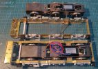
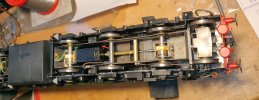
The outer frames are isolated from the inner frame by a piece of evergreen profile and two 3d-printed adjusting pieces epoxied in place. The outer frames can be removed from the inner frame with three small screws.
@Dave, I will add another 3d-printed part to protect the gearboxes from dirt.
@Richard, I followed your idea to add pickup from the isolated side. I like to use phosporous bronze wires that ride on the wheel flanges. This adds only very little friction.

I have also replaced the sand boxes with 3D-printed copies.


IMG_20230319_182635_cr_sml.jpg


Michael
 

Yorkshire Dave

Western Thunderer
Great work Michael.

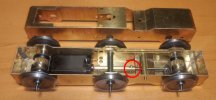
Coming back to an earlier photo of the drive truck is there any movement on the highlighted drive shaft joint?

I'm only thinking aloud as the right hand gear box as viewed is able to 'float' by means of the compensating beam however the entire drive shaft appears rigid with no apparent provision to provide or take up any movement when the compensation comes into play or the very slight fore and aft movement by the motor shaft and armature itself when changing direction.

otxx248p.jpg
 

michael080

Western Thunderer
Dave,
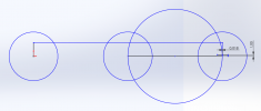
the motor-gearbox assembly can float freely around the wheel axis. The remote gearbox can float around its wheel axis as well. The connection rod is fixed and -- yes -- the distance between both gearboxes changes when the remote gearbox moves up- and downwards. However, the linear error can be neglected, it is only about 18µm. (see my primitive graphical illustration below)


Screenshot (531)_cr.png

Michael
 

michael080

Western Thunderer
so,
Spring was coming and a lot of things had to be done in the garden.
Now we have early summer and the mood didn't really return.
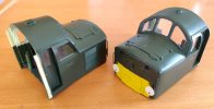
Anyway, I have finished the cab ends and now I am scared to pair them with the loco body, because the glazing and radiator grills are very delicate. The whole end units have to be finished, they will be soldered and glued to the main body.

I will try to build a protection layer of cardboard around the cabins to protect them from damage, but I will need to take courage to mate them.

IMG_20230602_171022_cr_sml.jpg

Michael
 

michael080

Western Thunderer
It took a few days to figure out how to hold the cabin ends in place, but I hope this will work:


IMG_20230608_214835_sml.jpg

I have one of these cheap lashing straps over the cabin ends to push ecverything together, foamboards between the cabins and the strap and a couple of strings to help positioning everything. Right now, the first corner has been fixed with epoxy, the others will follow later this evening. After that, I will have to solder the cabin floor to the main body.

Luckily, the lower edge radius of the body matches nicely with the cabins radius.

Michael
 

michael080

Western Thunderer
That closer look took a little bit longer...

The roof is made up of three separate panels that ride on teh struts seen in the last picture. Unfortunately it turned out that the main body bending radius was a little bit too narrow, so that the upper edge of the main body sits too low at that cabin ends. Lets see how it went:

IMG_20230708_235348_cr_sml.jpg

As you can see, there is a small gap at the right end of the panel that won't disappear.

Even worse the problem between the center and the fan panel.


IMG_20230730_180632_cr_sml.jpg

I had to fill the gaps with putty to make the worst problems disappear, but the transition between these panels looks bad. :headbang:


next problem, the louvre grids. The kit proposes to push individual slats through a comb with 0,3mm openings. The slats are about .25mm thick and 250mm long. There would be three combs on the way and the whole procedure would be after the roof is mounted. I don't think I could do that successfully, not even without some very loud shouting.

Here is what the problem looks like and what I made up to solve the problem.
One grid per window 3d-printed with max resolution. Much easier to fit and pretty good looking too.

IMG_20230802_153711_cr_sml.jpg

A first layer of etch primer went on the body. Next station is a week holiday in Brittany and then we'll see.

A question for the experts. The machine will be painted in its early green livery. I am wondering what colour the roof has, it seems to be a blueish light grey, but I hope somebody can provide a better description. The same applies for the narrow grey strip between the roof and the body.


Michael
 

Richard Gawler

Western Thunderer
A question for the experts. The machine will be painted in its early green livery. I am wondering what colour the roof has, it seems to be a blueish light grey, but I hope somebody can provide a better description. The same applies for the narrow grey strip between the roof and the body.

Similar stripes have received much discussion on the other channel. I did a search for "duck egg blue stripe" and found this post from last autumn:
Metro-Vick Type 2 Co-Bo - N Gauge

The idea of a grey strip which looks blueish in 1960s film emulsions sounds sensible. I am sure I have seen similar discussions there going back several years.
 

michael080

Western Thunderer
Standing on its own wheels for the first time.

Finally....

DSC07223_cr_sml.jpg

Painting was pretty disastrous. I was so upset that I dumped an almost full rattle can of Valejo varnish, because it gave a terrible orange peel surface together with runners. :shit: A lot of 2000 wet and dry removed the worst part of it, but I won't show you a close up of this engine, it is too embarassing. Varnish is my most feared opponent, it can ruin a lot of work in five minutes.

Michael
 

michael080

Western Thunderer
first update after 2 month of travelling, covid and a lot of other things that kept me from my workbench.

I am getting closer. The engine has been digitzed and is running very nice and smoothly in both directions. Looks like the concept with the motor between two gear boxes works as expected. This is now 1A1A-A1A1 or (1A1A)(A1A1) engine :)

I am using bronze wire pickups at the isolated wheels and pick up power from hte other rail from the isolated inner bogie. Both bogies are identical. The outer bogie frames are isolated from power as is the main body of the engine.

I hope to fix all bits and pieces later this week and have a couple of pictures of the complete engine in a week or two.


IMG_20231031_165358_cr.jpg

Michael
 

michael080

Western Thunderer
I think in green the cab roofs should be painted the roof grey.
Hi Brian,

Thanks for your friendly comments. I am well aware of your Flickr collections. They have been a valuable inspiration for my build.
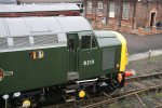
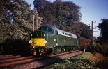
Reagarding the green/grey cab roof, I have the studied pictures in the book "The 40s" from Murray Brown. It has quite a few pictures of early green 40s, unfortunately most of them are so dirty that it is impossible to detect the cabin roof colour. Most engines with clean roof are grey as you propose, but I have a picture of my chosen prototype D211 that shows a very clean machine with a green cabin roof.

The copyright owner is David Christy and he doesn't allow downloads of his Flickr pictures, so here is a link to the picture:

www.flickr.com/photos/david_christie/6330685027/sizes/4k/


Kudos to you for handling the original cantrail grills. I couldn't. :oops:

Michael
 

daifly

Western Thunderer
The copyright owner is David Christy and he doesn't allow downloads of his Flickr pictures, so here is a link to the picture:
Downloading pictures (for personal use I emphasise) can easily be achieved. I find it easiest in Firefox:

'Tools' > 'Page Info' menu item

Click 'Media' tab.

Click the list and scroll down through it until you find the image.

Click the 'Save As...' button.

Dave
 

michael080

Western Thunderer
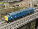
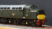
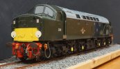
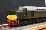
Finished!

It took a long time to get this kit finished. Now it's done and it needs to wait until next spring for some weathering.

DSC07304_cr.jpg

DSC07271_cr.jpgDSC07318_cr.jpg

DSC07274_sml.JPG

and finally the picture that inspired me to model D211. Copyright David Christy

40011 1965 EE Type 4 D211 Mauretania near Dunblane 26_8_1965 6330685027_532ffa09c7_b.jpg

The fine etched grille over the radiator outlet is currently painted for the fourth time. I didn't manage yet to paint it without blocking any of the 0.2mm holes. That thing looks very much like a electric razor blade.

Now it's time to clean up my cave before the next project starts.

Michael
 

michael080

Western Thunderer
This is my christmas gift to myself. A new project, a bit exotic probably.

I had a chance to purchase a 7mm kit of the quite exotic Bavarian class Pt2/3, later called class 70. This engine has the quite uniqe design (1B) with two coupled axis close together and a leading axle 4 metres away.
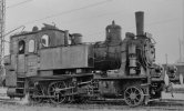
IMG_20231212_213809_cr.jpg

The engine had initially no bogey, only the last axle had side play.

Initially designed in 1909, the engines lasted into the 1960s before they were withdrawn. The idea of these light engines was that the fireman would also serve as a conductor. The engine had a door in its backwall to move to the coaches. The engine was specially designed to pull "light passenger trains" on main lines. In later years, it was ousted to branch lines. Some 50 of them were converted to have a "Bissel"-axle that improved its ability to negotiate tight curves. In fact, they were converted from 1B to 1'B .

I am planning to build the kit to reflect the appearance in the 1930s.


The kit has been desigend in the 1980 by Gerard, Vienna. Mr. Gerard sold his kits in monthly stages, my kit has 12 small leaflets that describe a months work. Most of Mr. Gerards designs were H0-kits, only very few 0-kits were sold. I could get one that was completely untouched. The brass will need a bit of glass fiber brush treatment, but it is of extraordinary quality.
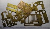
IMG_20231212_221335_crsml.jpg

These kits were very special at their time. They had some kind of bad reputation, because the H0-kits were very delicate and had some tiny components. People were saying "these are no kits, these are scaled down prototypes."

One of the most extraordinary components of the kits are the wheels. They are rim isolated with nickel silver tyres and brass cast wheel centres.
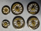
IMG_20231212_221721_crsml.jpg

But the brass casted parts aren't bad either, considering that they were produced 40 years ago.
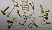
IMG_20231212_221620_crsml.jpg

I plan to present the progress in line with the kit stages, stay tuned...


Merry Christmas to all of you. This is a great community. I enjoy it very much to be a part of it.

Michael
 

Yorkshire Dave

Western Thunderer
Very nice. Exoctic to many UK eyes - one of the classic Bayern Nebenbahn loks.

I would assume as it a was produced by Gerard it would have been for the ÖBB 770. Does it have the original KBay.Sts.B coal bunker or the later DRG/DB hopper style and I presume you will be finishing it as DB to match your Br 78.

Fröhliche Weihnachten und ein gutes neues Jahr.
 
Top