You are using an out of date browser. It may not display this or other websites correctly.
You should upgrade or use an alternative browser.
You should upgrade or use an alternative browser.
7mm David Andrews Princess - 6206 Princess Marie Louise
- Thread starter Rob Pulham
- Start date
Rob Pulham
Western Thunderer
A few more micro fixings later saw. a major milestone both mentally and build wise.
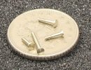
These are the pins which hold the eccentric rod to the bottom of the expansion link. Initially I made the two fully threaded versions but then realised that it would be better if they were only partially threaded (14BA).
I had already fitted the return cranks and after this it was a short step to getting the full motion running.
These are the pins which hold the eccentric rod to the bottom of the expansion link. Initially I made the two fully threaded versions but then realised that it would be better if they were only partially threaded (14BA).

I had already fitted the return cranks and after this it was a short step to getting the full motion running.
Chas Levin
Western Thunderer
A thing of beauty is a joy for ever... 

Rob Pulham
Western Thunderer
Hi Peter,Nice work Rob, but the way it started up in reverse would suggest perhaps that something may be binding.
Cheers,
Peter
It's my rather crappy controller which always seems to need more power in reverse than it does forwards. But it will be getting more of a run in on some actual track once I have the chassis finished.
Ian@StEnochs
Western Thunderer
RobHi Peter,
It's my rather crappy controller which always seems to need more power in reverse than it does forwards. But it will be getting more of a run in on some actual track once I have the chassis finished.
My bench controller is an old, very old, H&M unit which struggles to give much more than 6 volts and hardly any amps. However I persevere with it because I know that if a loco runs on it then it will more that satisfactory on a high end controller.
By the way I would be careful with your Harris wheels on the rolling road. Some have sharp hardened edges on the rollers and can score the soft iron tyres. Speaking from experience.
Regards,
Ian
Rob Pulham
Western Thunderer
Thanks Ian,Rob
My bench controller is an old, very old, H&M unit which struggles to give much more than 6 volts and hardly any amps. However I persevere with it because I know that if a loco runs on it then it will more that satisfactory on a high end controller.
By the way I would be careful with your Harris wheels on the rolling road. Some have sharp hardened edges on the rollers and can score the soft iron tyres. Speaking from experience.
Regards,
Ian
I agree with you re the controller, as you say if they run fine on that they will work on anything more modern.
Regarding the rollers on the rolling road, mine are thankfully not sharp, the Princess has by now, spent many hours trundling along on the rolling road with no signs of marking, but thanks for the warning.
Rob Pulham
Western Thunderer
Still beavering away making slow but steady progress. Next up were the front bogie top bearers (or that's how they are referred to in the instructions) and the fitting of the bogie itself. The former were easy, tin with 100 degree solder and use the RSU to heat from inside the frames.
The bogie fitting was a little more challenging. My fitting of the representation of inside motion had scuppered using the method that the kit provided. At Guildex I had a chat with Nick about how he had done his and he confirmed what I had thought would have to be the solution. Which is do it like the prototype (simplified of course) and fit a plate to the bottom of the frames. This proved challenging because of my seeming inability to drill a hole in the middle of a rectangular plate... It took three attempts before I got the hole in the ruddy middle. Actually, I am being a bit hard on myself. The first one was in the middle it’s just the plate was too small…
With the part finally ready to be fitted I turned my attention to the mounting screw and the 'nut'. The kit comes with a nice turned elongated top had type bush which is threaded 6ba in place of a conventional nut.
I had already made the side control springing block to accept this threaded bush so I wanted to use it. However now that the fixing point was much lower in the frames.
What I couldn’t work out was whether the bus was threaded all the way to the bottom of the hole or not because I didn’t have a long enough 6BA screw to check. So rather than trying to shorten the existing bush I thought it easier to turn up a new shorter version. I also turned the first 0.45mm to just fit tin the hole in the mounting plate which is slightly larger than the screw.
Despite my messing about for quite some time with a stack of washers trying to work out how long the shortened bush needed to be, it ended up slightly short.
Thankfully I had the foresight to leave it attached to the rest of the stock so once I worked out how much longer it needed to be, it was and easy job to turn another 2.5mm down to the same diameter. A short length of spring allows the bogie to float up and down by about 1mm.
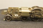
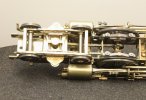
Having got this far there doesn’t seem to be much in the way of swing before it hits the inside of the cylinders but this may change when on track and the side control does its job. Time will tell whether I need to cut back the cylinder wrappers.
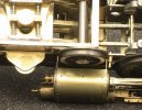
The bogie fitting was a little more challenging. My fitting of the representation of inside motion had scuppered using the method that the kit provided. At Guildex I had a chat with Nick about how he had done his and he confirmed what I had thought would have to be the solution. Which is do it like the prototype (simplified of course) and fit a plate to the bottom of the frames. This proved challenging because of my seeming inability to drill a hole in the middle of a rectangular plate... It took three attempts before I got the hole in the ruddy middle. Actually, I am being a bit hard on myself. The first one was in the middle it’s just the plate was too small…
With the part finally ready to be fitted I turned my attention to the mounting screw and the 'nut'. The kit comes with a nice turned elongated top had type bush which is threaded 6ba in place of a conventional nut.
I had already made the side control springing block to accept this threaded bush so I wanted to use it. However now that the fixing point was much lower in the frames.
What I couldn’t work out was whether the bus was threaded all the way to the bottom of the hole or not because I didn’t have a long enough 6BA screw to check. So rather than trying to shorten the existing bush I thought it easier to turn up a new shorter version. I also turned the first 0.45mm to just fit tin the hole in the mounting plate which is slightly larger than the screw.
Despite my messing about for quite some time with a stack of washers trying to work out how long the shortened bush needed to be, it ended up slightly short.
Thankfully I had the foresight to leave it attached to the rest of the stock so once I worked out how much longer it needed to be, it was and easy job to turn another 2.5mm down to the same diameter. A short length of spring allows the bogie to float up and down by about 1mm.


Having got this far there doesn’t seem to be much in the way of swing before it hits the inside of the cylinders but this may change when on track and the side control does its job. Time will tell whether I need to cut back the cylinder wrappers.

Richard Gawler
Western Thunderer
Having got this far there doesn’t seem to be much in the way of swing before it hits the inside of the cylinders but this may change when on track and the side control does its job. Time will tell whether I need to cut back the cylinder wrappers.
I read somewhere, the minimum radius on BR is 4 chains, which is 1,850 mm in 7mm scale. This being the minimum radius for any item of rolling stock on the network. I remember the four chains because the M&GN had a minimum of 3.5 chains . . . and was lost.
The model is so lovely, and will look so unhappy on even a 1,850 mm curve, it seems a shame to alter the cylinder wrappers unless out of desparation.
Clarence3815
Western Thunderer
I seem to remember the stated minimum radius for a Princess is 4.5 chains dead slow.
P A D
Western Thunderer
Very nice work Rob. I would agree with Larry on the clearance issue. It will be a shame if you have to cut back the wrappers, but if it won't run on the intended curves and that's the solution, why worry about something you can't see from normal viewing angles. Let's face it, very few models look 100% prototypical when viewed from the underside, what with the various chassis fixing screws, a big cog on the driven axle, the side control springs on the bogie, etc, etc. Pragmatism rules!I don't think there is any harm in removing some of the cylinder wrapper up to the three holes, afterall, nothing can be seen behind the drain cocks. Coming on nicely, the Lizzies had far more character than the later Pacifics.
Cheers,
Peter
Rob Pulham
Western Thunderer
I am working my way along the chassis adding the remaining details as I go. Two quite prominent features are the injectors. The kit included a nice brass casting for the live steam injector. This just needed some of the 'pipes' extending so that I can attach it more securely.
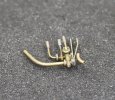
The exhaust injector was another matter as I couldn't find a casting for it so I had to buy one in. I had a look on Ragstone and LG Miniatures and the LG one seemed nearest to what I needed. Living out in the sticks as I do I was most impressed that I ordered it on Monday morning and it arrived yesterday lunchtime.
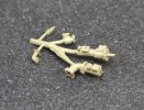
This is what you get from Laurie and the image below is what I need it to look like.
To completely misquote Eric Morecambe, 'Most of the right bits, but not necessarily in the right order'.
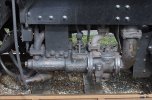
Sadly this means a bit of butchery is in order to get pipes facing the right way and one pipe joint that needs removing. The hardest thing about doing things like this is actually holding things to work on them. Luckily there are plenty of holes and spigots on the casting so a bit of work on a few offcuts of brass later and we have a few handles soldered on temporarily.
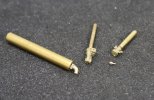
The small hex nut fitting is a part on one end that wasn't present in any of the castings, so I filed a hex on the end of a bit of rod and turned the spigots on it.
More to follow when I have it back to together.

The exhaust injector was another matter as I couldn't find a casting for it so I had to buy one in. I had a look on Ragstone and LG Miniatures and the LG one seemed nearest to what I needed. Living out in the sticks as I do I was most impressed that I ordered it on Monday morning and it arrived yesterday lunchtime.

This is what you get from Laurie and the image below is what I need it to look like.
To completely misquote Eric Morecambe, 'Most of the right bits, but not necessarily in the right order'.

Sadly this means a bit of butchery is in order to get pipes facing the right way and one pipe joint that needs removing. The hardest thing about doing things like this is actually holding things to work on them. Luckily there are plenty of holes and spigots on the casting so a bit of work on a few offcuts of brass later and we have a few handles soldered on temporarily.

The small hex nut fitting is a part on one end that wasn't present in any of the castings, so I filed a hex on the end of a bit of rod and turned the spigots on it.
More to follow when I have it back to together.
Sorry not sure what happened. There wasn't a post. Now deleted.Hello all,
what did Paul Cram have to say. Was his message missing?
A confused,
OzzyO.
Rob Pulham
Western Thunderer
I am almost at the point of reassembly of the exhaust injector, having added bits, chopped other bits off and repositioned the main elbow bend.
This is a small taster of what I have been up to.

First I milled a square section on the end of a piece of brass rod and drilled a 1.6mm hole in the middle and then a 0.6mm hole at each corner before taking it back to the lathe to part it off. This is the basis for a very visible pipe flange.
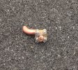
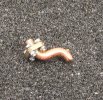
Then I made up some miniature fixings and soldered them to the copper pipe. The much magnified photos make it look much messier than it is to the naked eye.
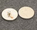
This is a small taster of what I have been up to.

First I milled a square section on the end of a piece of brass rod and drilled a 1.6mm hole in the middle and then a 0.6mm hole at each corner before taking it back to the lathe to part it off. This is the basis for a very visible pipe flange.


Then I made up some miniature fixings and soldered them to the copper pipe. The much magnified photos make it look much messier than it is to the naked eye.

Rob Pulham
Western Thunderer
This morning saw the injector back in one piece with all the right notes in the right order - for this loco at least.
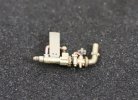
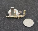
This was the set up for attaching the copper pipework using my RSU and cheapo self locking tweezers. Unlike many RSU users I don't use a steel plate to solder on to, much preferring to clip a smooth jawed crocodile clip to the part or the tweezers holding it.
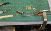
I do have one thing to work out and that's the bracket below. There are etched slots in the rear frame assembly for it but I am not sure at the minute how it attaches to the injector itself to allow it to mount. The other bracket which I have already attached is quite visible in the photo above to no issues with that one.
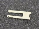
I also see from the photo that I need to clean up the etching cusp from it too if I plan to use it.


This was the set up for attaching the copper pipework using my RSU and cheapo self locking tweezers. Unlike many RSU users I don't use a steel plate to solder on to, much preferring to clip a smooth jawed crocodile clip to the part or the tweezers holding it.

I do have one thing to work out and that's the bracket below. There are etched slots in the rear frame assembly for it but I am not sure at the minute how it attaches to the injector itself to allow it to mount. The other bracket which I have already attached is quite visible in the photo above to no issues with that one.

I also see from the photo that I need to clean up the etching cusp from it too if I plan to use it.
Dave Holt
Western Thunderer
Very nice, Rob. Don't forget the water control rod carrying on up to the cab from the universal joint on top of the middle bit of the injector,
The front end of the injector was supported on a bracket that attached to two of the flange bolts holding the large bore exhaust steam pipe. You can see it in the colour photo you posted earlier. Perhaps the component you query is an attempt at that?
Dave.
The front end of the injector was supported on a bracket that attached to two of the flange bolts holding the large bore exhaust steam pipe. You can see it in the colour photo you posted earlier. Perhaps the component you query is an attempt at that?
Dave.


