Brettell Road, 1960s black country (ish)

Jim smith-wright

Western Thunderer
You guys know me by now. I dunno stuff I just copy what I see :D

7714-at-sheringham-on-the-north-norfolk-railway-september-2017.jpg
 

simond

Western Thunderer
A guess - possibly smoother braking action - with that arrangement offering some suspension dampening and potentially less stress to the horn guides?

i can’t see how it would help, particularly given that tank engines habitually operate in either direction, so an offset one way would see the block “leading” one way and “trailing” in the opposite direction.

Unbalanced brake blocks will always load the horns, unless they act straight downwards - this would obviously tend to unweight the springs and lift the loco of course. I’ve never seen such an arrangement, it would probably be detrimental to ride quality and track….

of course going one way a horizontal brake pull will translate to some unweighting and going the other, increased weighting on the springs due to the drag forces. Again, a minor offset will make little if any difference. I don’t think an offset pivot would substantially change the damping effects.

my guess is that it was to simplify the mechanical arrangement, but I don’t know what clearance was obtained/improved by offsetting the block pivots.
 

Giles

Western Thunderer
I would have thought the most noticable factor would be how much mechanical advantage you gain or loose by raising or lowering the brake blocks, and therefore how much effort the steam/handbrake applies.
 

michael080

Western Thunderer
If the wheel turns clockwise and the brake pad is on the right side, the actual brake force will be amplified if the pad is below the centerline. Nevertheless, as Simon mentioned, the wheel will be lifted.

However, I might be wrong. :confused:

Michael
 

simond

Western Thunderer
If the wheel turns clockwise and the brake pad is on the right side, the actual brake force will be amplified if the pad is below the centerline. Nevertheless, as Simon mentioned, the wheel will be lifted.

However, I might be wrong. :confused:

Michael
I think that would depend on the line of action of the drag force and whether it passed ahead or astern of the fixed lever pivot.

It's years since I did this stuff!
 

Jim smith-wright

Western Thunderer
Thoughts turn to the remaining detailing on the body of my 57xx tank. I like to take pictures pre paint for prosperity before it all disappears under plain black and grime and no one really notices what you've done anymore!

57xx-for-paint-front-3-quarter.jpg

Front 3 quarter view. You will notice that the buffers are different. Due to a timely new casting arriving from Lanarkshire models. Lamp irons are from Masokits and the sanding levers from RT models.

57xx-for-paint-LS-side.jpg

The footplate pipework has been replaced with wire The Whistle shield is from Modelu reinforced with a bit of wire. The tool box seemed a little 'floaty' as mainline had modelled it so I filled in the gap and re-scribed a finer one.

57xx-for-paint-rear-3-quarter.jpg

Rear view. The fire irons are from Springside Models and the rear windows from Mainly Trains (now Wizard models). I've thinned down the cab sides

57xx-for-paint-RS-side.jpg

I tried to do the water balancing pipe as one piece secured by magnets but as its all a little bit small the magnets weren't really strong enough. I had fears of it falling off and causing havoc with the inside motion so I had to settle for it being in 3 parts instead. Not sure what the little box is behind the rear footstep not all locos had them. I think it might be related to the AWS gear.

57xx-underside.jpg

Underside view - you can just make out the way the pickups are arranged.

My intended victim for this model was 8718 which in Brettell Lane era was a Kidderminster Loco. It later went to Stourbridge where it lost its number plates and gained painted on numbers in a reasonable attempt at the GWR font. I preferred the proper number plate. Searching for pictures I couldn't make out a BR logo on the tank sides. A request to the GWR modellers and British Railways Steam era 1948 to 1968 facebook groups didn't yield any answers either so reverting to my 'model what you see, not what you think you know' approach I left the logo off.

Below a few images of the finished loco. The crew are the customary Modelu products.

8718-@-Brettell-road-4.jpg

8718-@-Brettell-road-3.jpg

8718-@-Brettell-road-1.jpg

8718-@-Brettell-road-2.jpg


So there you have it - An unremarkable little tank engine.
 

Jim smith-wright

Western Thunderer
Let's start with a little observation. Modelling railways is expensive these days, the reason for this has been discussed elsewhere but if I were starting out now I certainly wouldn't be able to afford it. I actually think the prices are what they are but there are one or 2 things where manufacturers really are taking the mick.

Case in point is the 24ton LMS iron ore hopper. Firstly its not one, at all! Basically yes it is a hopper but thats about it. It's a loose model of the Charles Roberts hopper with a body stretched to fit a generic 10ft chassis. When you consider that this model first appeared in the 1977-78 mainline railways catalogue charging nearly £30 rrp for a completely wrong, very old tooled model is a fictitious livery is more than a little bit dodgy, Considering thousands of these are out there in various liveries for a fraction of the price you have to wonder who's actually buying the things?

So let's look at what this model attempts to be.

LMS hoppers are something of a gap in the RTR market as they have been hardly touched by either RTR or kit manufactures. I believe that the model is trying to masquerade as a diagram 1893-1942 iron ore hopper. From what i can tell these were all the same except for the materials used.

D1893 - 50 wagons built in 1934 by the Metropolitan Carriage, Wagon and Finance Company out of Chromador Steel

D1894 - 300 wagons built in 1934 by the trade out of mild steel

D1941 - 450 wagons built in 1936-38 by the trade out of copper bearing steel

D1942 - 100 wagons built in 1936 by the Gloucester Carriage and Wagon company out of an unspecified material.

Many of these lasted into the BR era and were cascaded to various steel works meaning theres quite a few liveries that can be done and an enterprising manufacturer can cash in on the current rise of interest in industrial modelling.

The model

While the RTR hoppers wheelbase of 10 ft is actually closer to the LMS wagons 10ft 6 than it is the Charles Roberts 9ft wheelbase theres nothing about the model that can really give you ahead start on constructing one of these so the easiest method is just to scratch-build one.

LMS-hopper.jpg

Which is what I did. Construction is plasticard with evergreen sections for the chassis and rivet strips from Mainly Trains or transfers from Archers. Buffers are from Lanarkshire models and underframe ironwork from Ambis and Bill Bedford. The axleguards, axle boxes and springs are salvaged from parkside kits. Drawings in LMS wagons volume 1 were used as a guide.

LMS-iron-ore-hopper.jpg

Painted up with transfers from Modelmaster and Fox.

iron-ore-hoppers-compared.jpg

Comparison with the Charles Roberts wagon on the right. This has been shortened and rebuilt on a 9ft chassis so its not a direct comparison with the RTR model as supplied. To see what I did to that one click Those little Mainline iron ore hoppers.
 

Jim smith-wright

Western Thunderer
This time we have a couple of classics from the Cambrian range

catfish.jpg

The good old catfish. Built with the use of Stenson models hand wheels and replacement handrails. One thing with these, as supplied, is that the wheels seem a long way away from the w W-irons, even in P4 so I cut the moulded rings off the back and moved the solebars closer together. A lot of people say these are a bit tricky but the only real difference to any other kit is you just need to take a lot longer and really let things set. They aren't really a bung it together in an afternoon style job. I found another 2 kits in my stash which i will build up for New Street and might do a bit of a step by step on how to do them.

mermaid.jpg

Next up the mermaid. I have built this as an early one which were the same as the original GWR builds. The main difference is push rod brakes instead of clasp, no vacuum brakes and earlier buffers. The rail clamps were replaced with Roxey mouldings shackles.

Below - It seems Brettell Road has had something of a GWR take over today!

GWR-takeover-1.jpg

GWR-takeover-2-bw.jpg

GWR-railcar.jpg
 

Jim smith-wright

Western Thunderer
Let's talk about glass. Something Stourbridge is particularly renowned for. It is believed that there has been glass production in the area for hundreds of years with a factory opening at the lower end of what is now Brettell Lane in the 1640s and production continuing in the area ever since.

moor-lane-goods.jpg
You're going to need your imagination for this bit! Regular readers will know that Brettell Road is not an accurate model of the real Brettell lane but is inspired by it and the local area. The above picture taken in August 2014 (that long already?) shows what was left of the goods yard at Moor Lane. Brettell Lane is behind us. The line to Pensnett branched off on the left and the yard is petty much straight ahead of us. You can see the flood lights against the skyline. This was the view from the left hand end of the original version of Brettell Road and is now the view from the middle looking to the right. On the model the line is not an S curve but a continuous left hand bend. Also the main line descends from this point on the layout while the real line rises as it goes away from us.

On the right, long gone now, there used to be a siding which served the Brierley Hill glassworks. The buildings are still there and can just be seen behind the trees in the distance where the mainline disappears.

Brierley-Hill-glassworks.jpg
Another view from 2014 that shows the building being converted into apartments. If you stand looking at the right hand end of the layout you would effectively be standing in this building. The line runs behind it and you can just make out the ironwork of Moor Lane Bridge on the right of the picture above the yellow van. This building is represented on the layout as part of the backscene.

Brierley Hill glass was more of the decorative, cut glass and crystal type than the industrial large sheets and I have a few shockvans as a nod to glass traffic but of course they could be carrying anything so only I know that. However thanks to a gift from my friend Tom i now have something a little more obvious...

coral-for-paint.jpg
I present you the ancient K's kit for the GWR Coral glass wagon. These were built in 1908, to 2 diagrams, by Swindon to carry large plate glass in crates. BR briefly continued with these building 6 more examples before switching to the LMS design but even then only building 42 wagons (also at Swindon).

I decided to build one of the BR types with the main differences being (as far as i can tell) the shape of the ends of the frames, the GWR ones being more curvy, and the brake levers. The model had been started by Tom's dad but was dunked in some cellulose thinners which dissolved the glue (but not the paint strangely) before it was reassembled using low melt solder. The kit had some nice brass buffers which were replaced with Lanarkshire models which better match the BR examples. The upper frames were cast in whitemetal and there were only 2 of them so they were replaced with brass section. A part of the original casting was soldered to the end of the underframe and reshaped to better match the BR design. I used the slotted bearing and central pivot method of compensation as previously used on my lowmac.

coral-finished.jpg
In service on the layout. As mentioned it's not really the sort of glass that Brierley Hill was known for but it is a nod to the industry. Apparently some of the real wagons were transferred to the steel industry anyway so perhaps its on trial in the area for that reason instead?

Thanks go to Tom and his dad.
 

bri.s

Active Member
Hi Jim

I’ve been looking but can’t find the answer
What is the baseboard dimensions for both parts of the layout altogether and separately ?
I’ve just bought some Tim horn baseboards and have been an admirer of the layout for some time and using it as inspiration for mine

Regards

Brian
 

Jim smith-wright

Western Thunderer
Hi Jim

I’ve been looking but can’t find the answer
What is the baseboard dimensions for both parts of the layout altogether and separately ?
I’ve just bought some Tim horn baseboards and have been an admirer of the layout for some time and using it as inspiration for mine

Regards

Brian
Hi Brian

The scenic boards are all 4ft but varying widths. This gives a scenic section of 16ft. The attached track plan may help.
 

Attachments

  • brettell road complete track plan.jpg
    brettell road complete track plan.jpg
    55.2 KB · Views: 59

Jim smith-wright

Western Thunderer
jinty-start-point.jpg
The Great British Locomotives Jinty. The model that started this whole diversion into the late 50s era. When they first appeared (as part of a magazine series) they were so cheap that I brought a second one just so I could do a before and after picture.

Recently I dug it out but I didn't want to just do another Jinty so my focus has been on its predecessor, the Johnson designed Midland 2441 class. Just for a little bit of clarity before we go any further both classes were referred to as Jinty's or Jocko's so going forward, if I mention Jinty's I mean the later LMS Fowler 3f.

So the 2441 class. The Midland built 60 of these which were considered as heavy goods tank engines. They were later rebuilt by Fowler which made them look very similar indeed to a Jinty. Initially there were 2 distinct types. with or without condensing apparatus. For those interested in these locos theres a good book on the subject, Midlands Engines No.5 by David Hunt, Bob Essery and Fred James (ISBN 1-874103-94-1)

The Model

Work required can be broken down into 2 areas. Stuff you might want to do anyway and stuff you will need to do to depict the 2441 class. Let's start with the stuff you might want to do anyway.

The handrails need replacing as do the lamp irons. The Chimney is a bit naff as are the safety valves and whistle. The coal rail is too chunky and the buffers are somewhat generic. The steps would benefit from something a little more refined.

For the 2441 specific bits the smokebox needs to be shortened and its saddle is a different shape. The Dome is also a different shape (more rounded) although I believe some had the more flattened off type. The front splashers are different too. The biggie is the tank sides which are taller and drop down by the cab area to be a little lower than a Jinty. The bunker is also lower and squarer with no overhang. The footplate is actually a little longer on these locos and the fairing at the ends is different.

footplate.jpg
So let's start with the footplate. The body of the model separates into 3 parts. The footplate, tank sides and bunker. The boiler, smokebox and tank tops and the upper part of the cab. Handily everything is plastic so carving it up is easy. I believe that the Bachmann Jinty has a cast metal footplate so it might be a bit more tricky.

The tank sides and bunker are from 30thou plasticard topped with microstrip. The coal rails come from my spares box (Brassmasters 1f etch) and the steps are from Mainly Trains. Splashers are also from Brassmasters (1f again) and the buffers and vac pipes are from Lanarkshire models. The lamp irons are from Stenson models. You can see at the back of the footplate where it's been lengthened.

cab.jpg
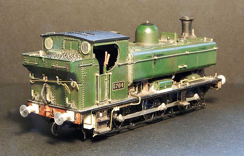
Not a lot to do the cab. New rear spectacle plates from Mainly trains.

boiler.jpg
The Boiler. I cut the smokebox back and remounted the front piece (which is separate). It seems that the condenser fitted locos had the handrail below the upper hinge like a Jinty but the others has it mounted above the hinge. Chimney is from my spares box (Brassmasters Jinty detailing kit I think) and the safety valves and whistles are from Markits. The top of the dome had been filled and blended into a new shape.

When it comes to the tank tops, the drawings show the filler caps to be more central and they certainly would need to be on the condensing locos as theres a big pipe in the way. However pictures of the non condensing ones show what looks like the bracket at the front of the tank indicating that they might be at the front as seen on the model.

ejecters.jpg
A little bit of fiddlyness for the ejectors. The moulded one is a bit clunky and I believe depicts a combined large and small Ejector. When I did my other Jinty I used a cast detailing part for this from (I think) London Road Models. Some 2441 class locos had these. The fiddly one depicts an earlier type and is cobbled together from 0.4mm wire with 0.6 and 0.8mm tubing.

2441-tank-mock-up.jpg
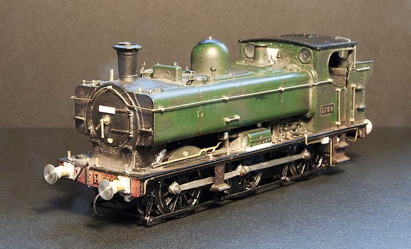
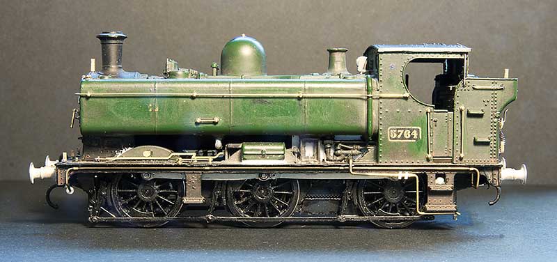
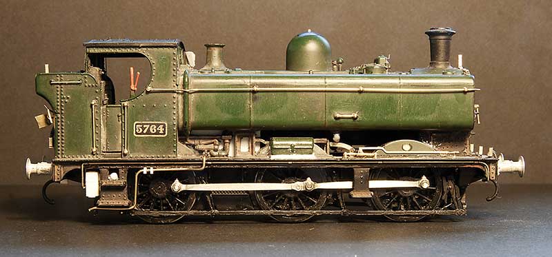
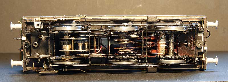
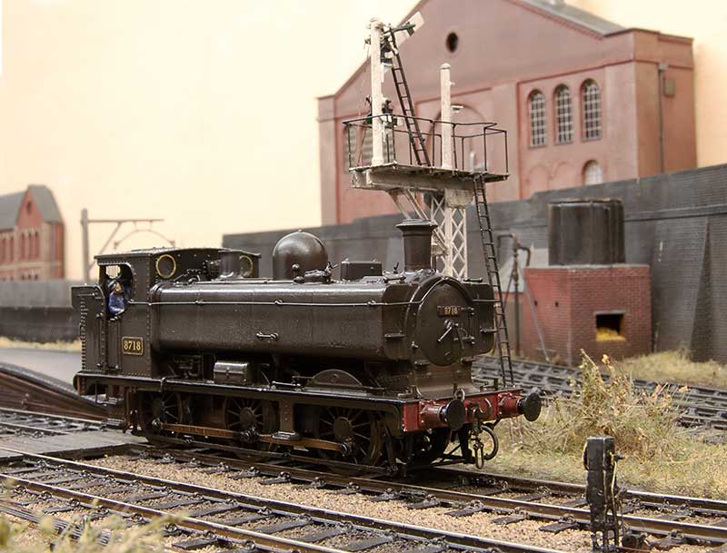
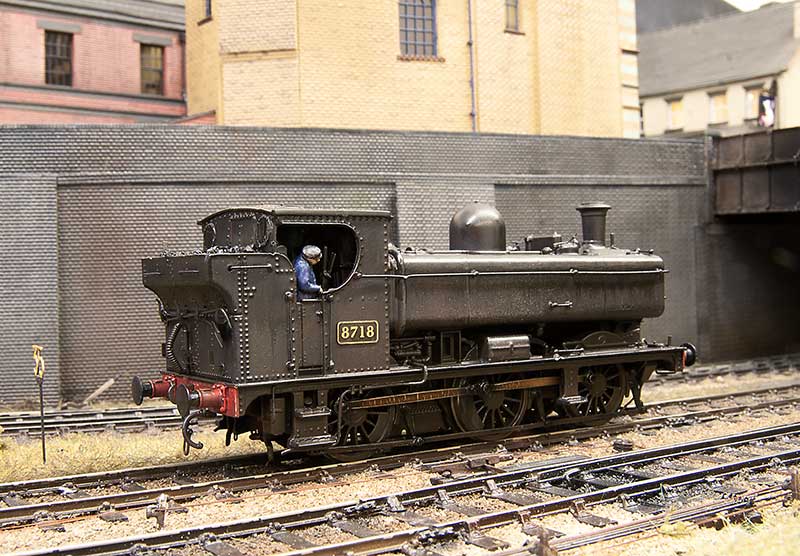
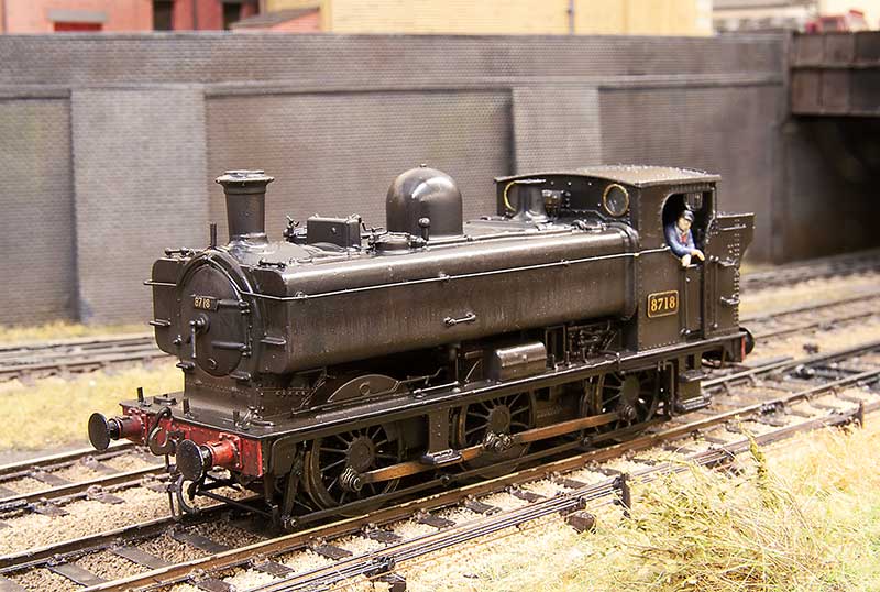
The assembled loco (so far) The chassis is a High level Jinty with the frames altered to be shallower. Otherwise it's built as per the kit. I didn't go for working inside motion as you really cant see it at all on these locos.
 
Top