And Now For Something Completely Different

JimG

Western Thunderer
For almost a year now, I've been looking at building a crane in 4mm scale for a fellow modeller in our club. It is to be a heavy wharf crane and we finally settled on copying the heavy crane at Tenterden station - shown in this picture

http://gallery.nen.gov.uk/assets/1007/0000/0188/this_is_a_goods_yard_crane.jpg

The one hang up I had was to source suitable gears for the crane. They are a prominent feature and you have to have something reasonably good or else the whole thing will look naff. I had looked at various adverts on Ebay for bagfulls of miscellaneous clock or watch gears like here but I was never quite sure if I would get the right size and look out of the hundred supplied. :) So I've had a fair bit of messing around this past week and I've put to use a bit of software I bought a year or two ago which generates files for cutting gears. The software is called Gearotic and it is probably best known for generating peculiar styles of gearing.

http://www.gearotic.com/

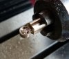
However, what it will do is generate standard gearing very well and I thought it was about time I had a go at using it - and the end result ids here

Crane001.jpg

The gears are actually cut to 0.2MOD - the smallest MOD size I could cut with the smallest milling cutter I had - 0.2mm (8 thou) diameter. The teeth are slightly too large - i.e. there are 90 teeth on the large gear and the prototype's large gear has about 120 teeth, but I think I will get away with that.

I had hoped to cut them in brass, but the spindle speed on my mill is nowhere near fast enough for very small diameter cutters, so I opted to cut them in Plastikard, where I can (almost) get away with slow feeds, and a wing and a prayer. :) The "almost" refers to the first cutter which went ping with the first feed speed I tried. :)

I also cut the main cast sides of the crane body in Plastikard, but I think I will redo them in brass since it will make construction of the body of the crane easier. I'm using larger diameter cutters for that and I might just get away with it. :)

I've also got to work out a way of cutting the two 10 tooth pinions required. Holding them to the end of the machining operation is the main problem but I think I've worked out a way of doing it.

Jim.
 

dltaylor

Western Thunderer
VERY Impressive bit of machining there Jim, please can we see the machine you made them on?
Many thanks,
Dave.T
 

Rob Pulham

Western Thunderer
Superb Jim:thumbs: ,

That looks so much better than the plastic main gear that came with my Medley Models crane kit.:'(
 

JimG

Western Thunderer
VERY Impressive bit of machining there Jim, please can we see the machine you made them on?

A not very good picture taken this evening of my Seig KX1 mill. I'll be out sailing all day tomorrow so had to knock off a quick shot under available light this evening. :)

crane003.jpg

Jim.
 

JimG

Western Thunderer
Superb Jim:thumbs: ,

That looks so much better than the plastic main gear that came with my Medley Models crane kit.:'(

Just had a go at a pinion - 10T 0.2MOD

crane002.jpg

But it's very delicate with the bore and the teeth roots very close. The second attempt partially collapsed.:) I'll make some more with a smaller bore, and have a look at modifying the tooth profile as well. Onwards and upwards. :)

Jim.
 

JimG

Western Thunderer
I had another go at the cast centre stand of the crane, but this time in brass. More accurately, I've had three goes. :) The first go was not too bad but I ran into problems with varying depths in the panelling cuts. I had done the big cutout round the shape before doing the detailing of the panelling and I noticed when doing the drilling that the brass was flexing - which would cause the variation in cutting depth.

crane004.jpg

The first attempt. You can just see that the recesses on the right are shallower than those on the left - particularly in the top end.

A second attempt was started, reversing the order of cutting to put the main cutouts at the end of the process. However that was aborted part way through when yours truly had a senior moment and forgot to set the tool height properly and started a cut with the tool about 10mm too low. Bang went the cutter and the shank dug a rather large hole in the work. I was also trying to be a bit clever on this cut to introduce bevelled inner edges on the relief round the edges but was having problems. I was using two tools to do the job and getting them set to exactly the same height was causing problems. It was during these problems that I dug the tool in. :)

So I went back to a simpler setup and had a third go, and that went a lot better.

crane005.jpg

This is the outline cut being made in the third attempt after all the relief details and holes had been machined. You can just about see the relief through the brass cuttings. You can also just see the aborted second attempt on the left.

crane006.jpg

The third, successful operation completed on the right and the unsuccessful second attempt on the left. You can see the ;largish hole made by the cutter shank on the lower left. :) The two parts in the third attempt are held in place by 0.2mm (0.008") thick tabs top and bottom, so have to be cut out with a piercing saw.

crane007.jpg

And the end result with liberal application of a coarse glass fibre stick to flat the brass down to stop kicks and flares in the camera. One small problem is the ridge in the upper left corner of the left hand part - a small ledge (less than a thou) left between the two surfacing cuts of the second and third attempt. I can smooth this down on a fine file, or I can just run another set of parts. :)

I'm much happier with brass since I can now construct the crane "body" by soldering, with the only plastic parts being the gearing.

Jim.
 

JimG

Western Thunderer
And a bit more has got done.:)

I haven't got a view of the crane that gives me some idea of what's between the cast sides so I assume that there would be a column up the middle that would sit on a big spigot, so that the crane could rotate, and that there would be cast spacers top and bottom onto which the cast sides are bolted.

So I started with the spacer for the top. I reckoned it would be basically tubular and be about a scale 4.5mm in diameter. So I turned up a length of brass in the lathe - over length so that I had about 10mm to hold on a chuck while working on it.

crane008.jpg

I then dug out my fourth axis and set it up. This looks like overkill for the job but it does allow me to work on both sides of a piece since I can rotate the piece exactly 180 degrees and still keep it in proper register. Also, holding such a small piece in a chuck is about the easiest way to do it. I've found that one of the main problems with a milling machine is actually being able to hold small work properly.

crane009.jpg

The spindle of the milling machine is lined up to the fourth axis in the "Y" direction. I'm also using a small Jacobs chuck to hold the piece - not normally an accurate way to hold something for milling, but I checked this small chuck out a year or two ago when I needed something to hold some 2mm scale axles and it had virtually no runout - so it was accurate enough for my purpose on this particular job. The small chuck also holds the job away from the fourth axis table to allow the milling head to get at the work with minimal overhangs.

Next was to cut the top of the piece.

crane010.jpg

The cutter is going through the action of cutting a circular cap, with a thin web to the outer flanges.

When the top side was finished, the fourth axis was rotated by 180 degrees to cut the bottom.

crane011.jpg

This was going to be a much simpler shape

And the finished item - top

crane012.jpg

and bottom

crane013.jpg

with a recess to take a spigot at the top of the central column.

The next act was to machine the central column on the lathe - with a nice long taper that had to be found by a bit of trial and error. The set over scales on the Cowells' topslide don't allow for too accurate setting.:)

crane014.jpg

I also cut a base for the crane but forgot to take any pictures.:) That was cut from 1/8" brass strip in a more normal way

crane015.jpg

All the central parts of the crane made so far, with the base lower right.

crane016.jpg

.....and a quick lash up on the vice to give an idea of how it will go together. The column looks a tad long, so a quick visit to the lathe will soon sort that out.:) I've still got to work out how to pivot the jib on the column, so there will be a pause for thought for a bit.:)

I'm quite enjoying this since it's making me use my grey matter to use the CNC mill in new ways (to me). :)

Jim.
 

JimG

Western Thunderer
I've now moved on to the jib of the crane which is wooden and octagonal and about a scale foot across the flats. I had a length of 9mm dowel lying around - originally bought to make handles for some very small diameter needle files. I had about six feet of it left over, so I was keen to put it to good use, albeit only for a few inches to make this jib. :)

Out came the fourth axis on the mill again. My intention was to hold the dowel in the fourth axis and rotate it 45 degrees between each cut along its length with a milling cutter - this to give the octagonal shape. I took the dog out for her afternoon walk and worked the code out in my head as we went along, and coded up when we got back.

crane017.jpg

The setup was similar to that for doing the top bracket, but this time my larger Jacobs chuck off the ML10 was pressed into service to hold the 9mm dowel. This would mean that I had to take any cutting quite easily since the 2MT taper on this chuck is a tang end with no drawbar facility, so it's only staying in its socket with the grip of its taper.

I started off with the 9mm diameter. I had thought about turning the dowel down to closer to the finished size, but opted to start at 9mm and let the machine bring the octagon shaping down from 9mm. If I turned the dowel to about 5mm diameter and it didn't chuck up concentrically on the mill - possible with wood - then the octagon could have uneven sides. The cuts being taken are 0.1mm (0.4 thou) to try and avoid deflection of the dowel at its extremity. I do really need a tailstock for the fourth axis to properly support long pieces, but I'll wing it on this job and hope that taking it easy gets a result.

crane018.jpg

The camera had difficulty deciding what to focus on. :) But you can see the octagon appearing. In this shot the distance across flats is about 7mm - a way to go yet. :) At this "diameter" there's not too much deflection yet, with both ends measuring virtually the same. When I get down to size, I'll run the tool at the same setting for several goes to work out any spring in the piece.

Jim.
 

mickoo

Western Thunderer
Bloody hell, and I thought I was being clever with CAD etches!

Thanks for the reality pill, mind it was an enjoyable one LOL keep up the outstanding machine work, very interesting.
 

JimG

Western Thunderer
I've been sorting out a problem on the milling machine for the past week - in between trying to do something about the jungle around my house. :) So progress on the crane was halted till that was sorted out. but I got things back into working order at the weekend and I started back into the work.

The octagonal jib shown earlier in the thread turned out to have a taper along its length which I found otu to be caused by my error in clampign the fourth axis to the table. So I sorted that out and machined another one, whcih worked this time.

I then moved on to the fitting at the top end of the jib. On the real life crane I'm using as a prototype, the top end looks like this

crane019A.jpg

...so I had a go at getting something close to this in brass. The fourth axis would be used again to machine four sides of the part.

crane019.jpg

A piece of brass rod was faced off to length then chucked up on the fourth axis and machining of the first side was started. Then one side of the circular head was cut.

crane020.jpg

Then the piece was rotated 180 degrees and the other side machined

crane024.jpg

...to give a finished round shaped base for the head

crane025.jpg

I then added some detail in the head - a much simplified version of the real thing, but this was the first attempt at it. :)

crane026.jpg

This was done on both sides of the head then the part was rotated by 90 degrees to start forming the gap for the pulley

crane028.jpg

...with the first half of the gap formed.

crane029.jpg

The part was then rotated 180 degrees to machine the other half of the slot

crane030.jpg

...and the final result with the slot fully cut for the pulley

crane031.jpg

And now the part out of the chuck before heading for the lathe to finish off. I keep forgetting that parts need to be cleaned before taking 10x macro shots. :) The head has also gained centre holes for drilling for the pulley shaft, which was the last act on the milling machine.

crane032.jpg

The part was now chucked up in the lathe and the spigot which inserts in the wooden jib was turned. You can just about see the milled part in the chuck jaws.

crane033.jpg

The part was then reversed and the taper part was turned with the topslide set over

crane034.jpg

And finally the completed head fitted in the octagonal jib

crane035.jpg
It's a comparatively simple rendering of the real thing but I think it gives a fair representation. I'm already thinking about ways of representing the more complex casting of the prototype but I think that might have to wait since it will probably take a fair amount of time to experiment with the ideas and I have got a load of other things to do (including the garden/jungle). :) But it has been a good experience in doing full 3D cutting on a fairly simple four axis setup with unsophisticated (i.e. cheap :) ) software.

Jim.
 

Attachments

  • crane027.jpg
    crane027.jpg
    80.3 KB · Views: 6

40126

Western Thunderer
Hi Jim :thumbs:

How long did that take (item in pics) from start to finish ?. ;)

That looks amazing.

Steve :cool:
 

Steve Cook

Flying Squad
Brilliant work Jim, and thank you for the step by step photos :thumbs:
I don't have a rats chance of following them (machine wise), but you are providing motivation by the bucket load to go and make stuff...
I have tool (and skill) envy, must go practice :)
Steve
 
S

Simon Dunkley

Guest
It seems a shame that all this effort is going into a one-off. Any chance of you using the pieces as patterns for casting?
 

JimG

Western Thunderer
How long did that take (item in pics) from start to finish ?. ;)

Steve,

The machining time in the mill is estimated at 25 minutes in the CNC software and that's pretty accurate. Add another 5 minutes for setup and tool changing and about 15 minutes work in the lathe, and it comes in at around three quarters of an hour.

I went on and machined the bottom bracket this afternoon and that took a bit longer although I could have shortened the milling time once I had seen what was going on. I had been playing safe in several areas and could have tightened up on those areas. It would have taken about 55 minutes to do the bottom bracket. Here's the final result of the bottom bracket.

crane036.jpg

And to show that not all went well - the scrap heap from this afternoon.:)

crane037.jpg

All were scrapped due to alignment errors down to me getting too confident about my so called prowess. :)

It was probably overkill to take an hour to make this fairly simple piece on the machine when I might have made a similar piece on the bench with saw and files and a small amount of lathe work in less total time. But it was worth doing it just to learn lessons about dealing with waste material - the outer bits on the scrapped pieces above - which can have a severe effect on the life expectancy of small diameter cutters if you haven't made provision for them. :)

Here's the final jib assembly with all three parts dry assembled.

crane038.jpg

I've now just got to fit a bearing mount for the jib on the crane body and I can start making an assembly of the crane. But the garden calls tomorrow, so the crane might get a rest for a day or two. :)

Jim.
 
Top