3D Printing a Early GWR Wagon Body

ICH60

Western Thunderer
Hi
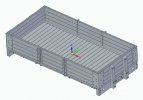
I have over the past few months been producing in Fusion360 an early 1 plank wooden under frame GWR wagon. My period is 1898 so I have a requirement for a few 1,2,3 and 4 plank wagons. This is a test to see what I can get out from my own 3D printing and to that end I final bought a Saturn2 8K printer.
The model is based on photographs ( there is not many) and information in various books, GWR Goods Wagons Atkins, Beard& Tourret and the Saltney Carriage and Wagon Works by T Wood mainly
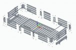
The model was designed at full scale and then reduced to 7mm. The floor will be printed separately and fit inside the body. The idea is that the W irons, coupling hooks brakes will be etched, the buffers and axle box springs will be either printed or bought dependant on the state of repair over the years.
This was really a proof of concept rather than a final version. Still learning the best way to produce models in 360 there was a lot of 1 step forward two step back, and there will be changes from what I have learnt so far.

Render of the 3D model1 plank wagon.jpg
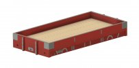
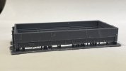
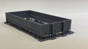
So last night I had a go at printing. Bit of a crash course in Chitubox, used the standard settings for the resin, I used Siraya Tech Fast, there were lots of extra supports and printed at 35um
I decided to print with the body parallel to the build plate as this was recommended by ianlbsc at the S7 Northern meeting.
So the first attempt failed at the start of the body after the supports. I forgot to take of the plastic protector of the build plate!!!!
Second attempt went well.
IMG_6935.jpg

IMG_6934.jpg
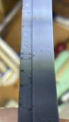
For some reason some of the supports seem to disappear. Not sure why?

Also there were lines on the bottom half of the model though very fine but not on the main body. Again not sure why?
IMG_6938.jpg
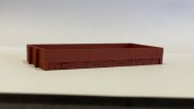
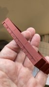
I have now cleaned up the model and I have sprayed the model in Halford Red Primer. This is what I think GWR wagon red was
IMG_6939.jpg

IMG_6943.jpg


The bolt detail has come out well

I have to say that I am pleased with result. There are a few things to change on the next model one of which is a more defined gap between the different pieces of wood. I just used a fine chamfer on on edge.
 

Rob R

Western Thunderer
A very good first attempt.
I can't help you with the disappearing supports, try re-doing the supports from scratch.
It may be worth adding a small scarificial strip all around the underside of the headstocks and solebars, you can then stick the supports to that and sand back after printing, only needs to be 10 thou thick (0.25mm in new money) and you can have as many heavy supports as you like without worrying about the appearance.
As you have probably noticed, the lines vanish under a coat of paint and I wouldn't bother about printing the floor, large flat bits are a pain, plasticard/ply/brass are your friends there.
For the plank detail, in 1/64 I use this section:-Pos and neg cross section of GNR open Note it is upside down in that view.
Good to see the bin monster go hungry :)
 

simond

Western Thunderer
Looks good!

have you considered printing the buffer stocks as part of the buffer plank? I took that approach with my Mica chassis.

and I also forgot to take the protective liner off the build plate on my first attempt…
 

ICH60

Western Thunderer
A fine result!
Can I ask what printer / resin you are using?

Peter
Thanks for the kind remark
I am using a Saturn2 8k and the resin is Siraya Tech Fast Navel Gray. I just used the setting download off their web site into Chitubox.
 

ICH60

Western Thunderer
Looks good!

have you considered printing the buffer stocks as part of the buffer plank? I took that approach with my Mica chassis.

and I also forgot to take the protective liner off the build plate on my first attempt…
Thanks
The buffer stock changed through the life of the wagon so I keeping them separate.
 

JimG

Western Thunderer
I have to say that I am pleased with result. There are a few things to change on the next model one of which is a more defined gap between the different pieces of wood. I just used a fine chamfer on on edge.

I've used a chamfer on both bits of wood and often did a test with varying chamfer dimensions to see what gives the best result. In Fusion 360 you can set up the chamfer dimension as a variable so that you can adjust all the chamfers in one action by changing the variable.

I've started using Solid Edge and I haven't worked out if I can do the same, but I'm now building planked wagons with individual planks being assembled into the finished body so I only have to adjust the chamfers on the base planks.

Jim.
 

Dog Star

Western Thunderer
I've started using Solid Edge and I haven't worked out if I can do the same, but I'm now building planked wagons with individual planks being assembled into the finished body so I only have to adjust the chamfers on the base planks.
Jim,

I am not sure what you are doing as described above... one possibility is that you are taking individual, scale size, wooden planks and constructing the side of the model one plank at a time... another possibility is that you have drawn a plank with chamfer with your 3D program and then doing a copy and paste to build a 3D model with the sheeting made from pasted copies of the original drawn plank.

Please help to understand.

regards, Graham
 

JimG

Western Thunderer
Jim,

I am not sure what you are doing as described above... one possibility is that you are taking individual, scale size, wooden planks and constructing the side of the model one plank at a time... another possibility is that you have drawn a plank with chamfer with your 3D program and then doing a copy and paste to build a 3D model with the sheeting made from pasted copies of the original drawn plank.

Please help to understand.
Sorry Graham, I suspected that I might have streamlined the description into nonsense. :)

Taking the side of a standard wooden wagon with a side door, the planks on each side of the door are the same length so one base side plank can be placed four on each side of the door to start a side for a Caledonian Diag.24 open. Then there is a base plank for the door which can be placed four times to make the door. Therefore I can build up a side of the wagon using two base planks and these planks can have whatever chamfering on them to give the wood join effect. And these two base planks will do the other side. For the ends, one base plank will suffice to build the two four plank ends, again with what chamfering is deemed necessary. So three base planks to do all the wagon sides.

I've followed this method since Solid Edge encourages assembly of complete models by using parts. Once you have assembled a model, you can go back and adjust a part and the adjustments are automatically carried through onto the assembled model.

WagonAssembly-01.jpg


Here's the Solid Edge model of the Caledonian wagon with all the sides from the three base planks. The body is built up on a rectangular base made of the curb rails and the two end curb rails. The floor planking is made from one base plank repeatedly placed within the curb rails. The side planks are built on the curb rails.

And all the parts are appropriately chamfered to make the joints obvious. If I have to adjust chamfers I only have to do it to the base parts and these changes automatically reflect through into the assembly. One of these days I might find a way of using variables like in Fusion 360 so that I only have to change one value to change all the chamfers. :)

Jim.
 

Dog Star

Western Thunderer
Ken,

Thank you for the enhanced description and I understand your approach now. I think that talking about "base" planks confused me... was this a plank at the base of the side? or was a base plank the basic component of the drawing; now clear and understood.

regards, Graham
 

Dog Star

Western Thunderer
Well Jim, that last post certainly shows what you have done, so potentially useful that my Son Peter (aka Spike here) has just checked to see what Onshape offers and it does, called "exploded view". I can see us using this approach where replication is a feature of the design.

thank you, Graham
 

ICH60

Western Thunderer
A very good first attempt.
I can't help you with the disappearing supports, try re-doing the supports from scratch.
It may be worth adding a small scarificial strip all around the underside of the headstocks and solebars, you can then stick the supports to that and sand back after printing, only needs to be 10 thou thick (0.25mm in new money) and you can have as many heavy supports as you like without worrying about the appearance.
As you have probably noticed, the lines vanish under a coat of paint and I wouldn't bother about printing the floor, large flat bits are a pain, plasticard/ply/brass are your friends there.
For the plank detail, in 1/64 I use this section:-Pos and neg cross section of GNR open Note it is upside down in that view.
Good to see the bin monster go hungry :)
Interesting what you said about the floor. I will see what happens
 

SimonT

Western Thunderer
Ian,
good to see a second one planker in captivity; very impressive. The other one in the Brokenborough stock box, built in Kuwait while not aviating. Are you going to do a bulb section underframe wagon?
Simon
 

ICH60

Western Thunderer
Ian,
good to see a second one planker in captivity; very impressive. The other one in the Brokenborough stock box, built in Kuwait while not aviating. Are you going to do a bulb section underframe wagon?
Simon
Morning Simon
Not planned at the moment. The plan is to make 2 and 3 plank versions plus a wooden framed covered wagon and cattle wagon. Might then move over to a bulb section versions, but that might be a etched under frame.
Though this will be but on hold, as I about to start the building of the track work on Shipston on Stour which will keep me busy!
Ian
 

SimonT

Western Thunderer
Greetings,Ian,
I look forward to seeing these projects. Are you going to do the brake van too? I've got drawings of most of these from when I did that work for the GW Study Group on the back of Brokenborough. Yell if you want copies.
I did the bulb solebars as resin castings off a master. Behind the resin were Evergreen strip solebars and chassis.
I ought to do some repairs to all that stock. The brake van running boards have fallen off, the cattle van plastic brake shoes have disappered, etc, etc. Bloody Tempus! On which note, good to hear the track is going down.
Simon
 

ICH60

Western Thunderer
Greetings,Ian,
I look forward to seeing these projects. Are you going to do the brake van too? I've got drawings of most of these from when I did that work for the GW Study Group on the back of Brokenborough. Yell if you want copies.
I did the bulb solebars as resin castings off a master. Behind the resin were Evergreen strip solebars and chassis.
I ought to do some repairs to all that stock. The brake van running boards have fallen off, the cattle van plastic brake shoes have disappered, etc, etc. Bloody Tempus! On which note, good to hear the track is going down.
Simon
Simon
Not at the moment. The service at Shipston was mixed trains so to my knowledge they didn't use them. Though happy to be told otherwise.
Never say know to more information.
Yes the passage if time, like my body, things start falling off or going wrong :D
How's your layout coming along?
Ian
 

paratom

Western Thunderer
A nice result and probably no better than you would get at Shapeways. On my 3D prints I try and get away with not using supports if I can as I find then awkward. With supports you always risk damaging the surface they are attached when they get removed and then there is the extra time involved in hiding the marks left behind by them. For a wagon like the one you printed I would try printing it bottom upwards with the top of the solebar resting on the build plate. Now you might be wondering how you get the wagon off the build plate. If you have printed small items like axle boxes this way you can just give them a sideways tap and they will pop off, anything like your wagon could get damaged if you tried this. There are thin magnetic plates that you can attach to your build plate which you just take off the build plate after printing and bend to get the print off. You will have to recalibrate the printer if you use one of these. I myself have been tempted to try this method but instead use an old fashion razor blade which I gently slide under the item in order to remove it from the build plate. If you do go down this root leave the item on the build plate until it has cured. The reason for this is so the printed item doesn't warp as it is curing which it can sometimes do when it's off the plate. I have a cheap spray gun that I use to spray the items with if you need to use isopropanol. I use a washable resin these days, makes cleaning the model much easier and you can just hold the build plate under a tap as you clean the item. This all works for me but only after a lot of experimenting and might not work for other people. So the 45 degree rule when 3d printing with supports in which you waste a lot of time and material can be dispensed with on a lot of occasions.
 

ICH60

Western Thunderer
A nice result and probably no better than you would get at Shapeways. On my 3D prints I try and get away with not using supports if I can as I find then awkward. With supports you always risk damaging the surface they are attached when they get removed and then there is the extra time involved in hiding the marks left behind by them. For a wagon like the one you printed I would try printing it bottom upwards with the top of the solebar resting on the build plate. Now you might be wondering how you get the wagon off the build plate. If you have printed small items like axle boxes this way you can just give them a sideways tap and they will pop off, anything like your wagon could get damaged if you tried this. There are thin magnetic plates that you can attach to your build plate which you just take off the build plate after printing and bend to get the print off. You will have to recalibrate the printer if you use one of these. I myself have been tempted to try this method but instead use an old fashion razor blade which I gently slide under the item in order to remove it from the build plate. If you do go down this root leave the item on the build plate until it has cured. The reason for this is so the printed item doesn't warp as it is curing which it can sometimes do when it's off the plate. I have a cheap spray gun that I use to spray the items with if you need to use isopropanol. I use a washable resin these days, makes cleaning the model much easier and you can just hold the build plate under a tap as you clean the item. This all works for me but only after a lot of experimenting and might not work for other people. So the 45 degree rule when 3d printing with supports in which you waste a lot of time and material can be dispensed with on a lot of occasions.
Thanks Paratom. Well I think the results are better that Shapeways. Obviously there is a large initial outlay but then the prints cost very little.
As to printing, I went with printing upwards as the top of the wagon has the fine metal strip which was used to protect the body, which could be easily be removed when sanding. I went for the approach that I would support the bottom as you can easily sand the supports off. I just removed any supports in Chitubox that were connected to the side of the print and to any bolts which it randomly put on some, and added loads more supports under the body with no real plan. In fairness as its a wooden frame body its is fairly chunky. But it was my first go so I didn't really know what to expect. To be honest I wasn't really expecting it to work. I will not let it stand for a week or two and see if any warping happens.
Removing from the plate was very easily as well, but that maybe its a brand new plate. I have only just heard of the magnetic plate so I might get one and experiment with it.
I have to say it was a lot easier than I thought it would be. I would say it worked straight out of the box.
 
Top