You are using an out of date browser. It may not display this or other websites correctly.
You should upgrade or use an alternative browser.
You should upgrade or use an alternative browser.
Wills T9 Repair and Upgrade in 4mm 00 Gauge
- Thread starter Stevers
- Start date
Overseer
Western Thunderer
Looks much better but the handles were usually tapered so if you want to take it a little step further you can use tapered case pins from a watchmaker or jewellers supplier. Similar tapered pins are available in steel and sometimes nickel silver if you need the polished steel look. The box contains a range of thicknesses and tapers, from nearly nothing to a bit over a millimetre. Very useful for tapered handrail stanchions for earlier loco cabs as well.

Stevers
Western Thunderer
Good tip. The handles on the real 311 look straight and unrealistically thin in my reference photo, but not impossible that there was a taper on them - I shall do some more research. If they do have a taper I will know what to do! Martin Finney pointed me towards N/S clock pins for use as cab handrails and I probably used them for the first time on this build. I had thought the ones I'd used were the thinnest in the pack, but then I found some that were so fine I could hardly see them. The thicker ones in the pack went to a couple of 7mm scale modellers in the Yeovil Group.
The 'Daddyman Dart'
")
Tim Hale
Western Thunderer
Just before someone mentions the Southern on the tender being incorrect, it is a temporary fix until the ‘new’ tender body pitches up. The loco will join the others in the usual hybrid livery of Southern and BR, as 30311 but without snifting valves (removed a few months before withdrawl) as the loco AFAIK never received BR mixed traffic livery. The image below was taken at Fratton in ‘48, the last known image of 311 from the John Derry book.
BR

BR
Attachments
Last edited:
Stevers
Western Thunderer

Far too long was spent on the lamp irons for the running plate! First attempt was to solder brass lamp irons from the Mainly Trains fret as per the smokebox door. After carefully preparing them including tinning them first with electricians solder, I couldn't get enough heat into the white metal to get a strong bond. The half etched folds even when reinforced with solder seemed flimsy, so a plan B was called for. To match the width of the etched lamp irons I used some thinned down staples intended for a staple gun, put a joggle in them and epoxied them into the running plate with the two bolt fixing plates from the failed brass lamp irons notched, and epoxied behind them. Mindful of wanting to do another Wills T9 for myself, I made a jig to put the holes in the same place. They're perhaps a little tall still, but at least I can do something about that.

Fairly randomly the boiler handrails were tackled next using 0.4mm piano wire. Nothing is glued in, but the Branchlines short handrail knobs do not look to be as delicate as the AGW long handrail knobs, so I'll be using my supply of short AGW knobs for the next fitting. The short handrails not being fully home in this shot, and the good news is that once glued the holes in the short and long handrails do seem to line up nicely with the holes in the cab front and therefore the handrail will be straight, just needing a few tweaks to the bends over the smokebox door.
Stevers
Western Thunderer
To enable the pickup block/ashpan to be removed the brake gear needed to be removable. The normal way of doing this is to use tubes into the frames, and because I'm retro-fitting them the method adopted is a variation of that. First step was to stiffen the pull rods and cross members with microbore tube so that the bottom was nice and stiff and robust looking. Then the 0.7mm cross wires were snipped at around 1mm from the frames and short lengths of close fitting microbore pipe soldered onto the stumps to space the hangers from the frames. There was an element of faffing around to get everything straight and parallel afterwards, and it would have been easier to have designed this in from the start, but this is my first removable brake assembly. The single pull rod at the back is centred on the rear crossmember with a couple of strips of 0.3mm wire that are just visible.


Also visible are the tops of the sand boxes fabricated from solid brass, and the sand pipes that mount on the tab that secures the chassis at the front. This arrangement makes staying the springy phosphor bronze pipes tricky, but that is really what needs to happen, and there is likely to ba a Z shaped plate to take the stays in the next iteration. With DCC there is no tolerance for the little shorts that aren't noticeable in DC so best to leave a bit of room round brake gear and sand pipes. Prior to painting there will be some epoxy resin spread in vulnerable areas.

Inverted power pod with brake gear and sand pipes fitted - a credit to the designer of the chassis!
Also visible are the tops of the sand boxes fabricated from solid brass, and the sand pipes that mount on the tab that secures the chassis at the front. This arrangement makes staying the springy phosphor bronze pipes tricky, but that is really what needs to happen, and there is likely to ba a Z shaped plate to take the stays in the next iteration. With DCC there is no tolerance for the little shorts that aren't noticeable in DC so best to leave a bit of room round brake gear and sand pipes. Prior to painting there will be some epoxy resin spread in vulnerable areas.
Inverted power pod with brake gear and sand pipes fitted - a credit to the designer of the chassis!
Tim Hale
Western Thunderer
As the new owner of the T9, I am very pleased by the dedication evident in this build. I doubt if my father would recognise his loco but he would appreciate both the skill and innovative approach. My role is to try to interpret what he intended, his interest was the SDJR and T9s were an everyday occurrence.
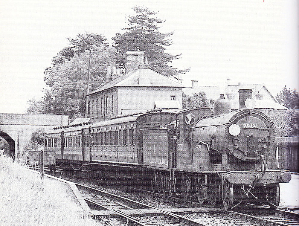
Fordingbridge station, a T9 on a down service with an SECR articulated set in tow, Dad captured it at Eastleigh and it was early BR carmine. It wandered extensively, including the regular workmen train to Idmiston that started at Bournemouth West as well as forays down the Fawley branch, needless to add it escaped preservation.
Tim
Tim
Stevers
Western Thunderer

Making this was extremely time consuming - there must be a better way! Probably a fraction overscale, it is based on a photo of an injector on the preserved T9 when it was at Ropley. One more to do for this Wills T9, two more for my Wills T9, and there are two other T9s in the pipeline, so that's another four - ouch!
[Edit] I should add that it's made from two sizes of microbore brass tube and 24SWG (0.56mm) phosphor bronze wire. The cold water inlet and exhaust pipes are attached on the 'Daddyman Dart' principle.
Last edited:
Stevers
Western Thunderer
A few days ago the second injector snapped in two when the bends were put in so that set me to overthinking the problem. With a number of injectors to make it seemed to me that a jig was required to drop the holes consistently in the same place, but to do that I needed a much better answer as to how big these things were, and in particular just how far apart those pesky holes should be.

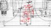
To do this the GA from Bradley was scanned into QCad and scaled using the wheelbase dimension (the Eastleigh one, not the Wills one). Next a simplified version of the injector seen at Ropley using materials that I had to hand or could reasonably make, was superimposed on the injector shown on the GA. The body required 1.3mm tube that I didn't have, so a length of that was turned in a mini-drill from 1/16" brass tube using a small bastard file to do the cutting. Next I took a length of 3/32" brass tube, inserted some 1/16" tube and soldered it in. This was then drilled out to 1.3mm ready to receive the body tube. The holes needed to be 1.5mm apart about 0.5mm from the end - I'm not capable of working to the 2 decimal places shown! My manual riveter (with drop weight) was used to centre pop the holes in the jig tube at the correct distance and the holes were drilled at the correct distance apart - this took two attempts. A fret saw was used to cut a slot for the end stop that also assists in aligning the tool in my pattern makers' vice.

The tube for the body can then be inserted in the jig, restrained by my other pattern makers' vice, and the holes drilled. Once the body has been trimmed to the correct length the end with the exhaust needs to be opened out to 0.9mm to receive a short length of 0.9mm tube bored out to 0.55mm to take the 24SWG wire. Adjust length of this wire and the rebate until the length exposed suits. The short length is likely to overlap the hole, so once all is soldered together the exhaust hole can be drilled a little deeper again

The bend for the cold water feed is quite close to the injector body, so the wire was bent first and a short length of 0.9mm tube threaded on before it was trimmed to length from a photograph and soldered in. The exhaust pipe required a 0.5mm length of 1.3mm tube that was squashed onto the wire to represent the flange shown on the Ropley photo which differed from the arrangement shown on the GA. The bends (which differ between 700 and T9 classes) could then be applied with no danger of anything snapping. These are the T9 style bends. Extra marks would be given for anyone turning some extra detail into those tiny bodies! Parallax error or a bendy steel rule - I'll let you decide.

In other news the gap at the top of one of the cab sides has been almost invisibly filled in. Also shown is the 'Southern' sunshine branded tender intended for 311. Looks like I do get to redo the handrails on the tender after all, at least one of the toolboxes is loose and the supremely delicate and vulnerable plastic top lamp bracket at the back is missing and needs replacing with something robust (and much more dangerous) in steel. In the foreground is a jumble of injectors, injector related pipework and boiler handrail that makes it look more like it's being scrapped than built!

Next we have a bit of an experiment. Perched a little wonkily on the firebox in front of the cab is my cab front, that has been fitted with brass tube framed windows with glazing of the correct diameter made with a 5mm hole punch. Whilst my execution of the idea leaves something to be desired, there's definitely potential there for a much improved look to the cab, and short of acquiring or making another cab front, there's no going back for my T9!

Lastly crossing my workbench for a bit of TLC is this EM Gauge Wills T9 with a Perseverance chassis from the hand of the late Bob Okesford. The loco is compensated on the Flexichas principle with an RG4 (not seized) driving the fixed rear axle. This arrangement required a backhead of prodigious proportions to conceal the chunky gearbox. The centre of the cast running plate had been removed to accommodate the full length chassis with the result that the ride height is not so very far off. At least thirty years old and close to leading edge when built.
To do this the GA from Bradley was scanned into QCad and scaled using the wheelbase dimension (the Eastleigh one, not the Wills one). Next a simplified version of the injector seen at Ropley using materials that I had to hand or could reasonably make, was superimposed on the injector shown on the GA. The body required 1.3mm tube that I didn't have, so a length of that was turned in a mini-drill from 1/16" brass tube using a small bastard file to do the cutting. Next I took a length of 3/32" brass tube, inserted some 1/16" tube and soldered it in. This was then drilled out to 1.3mm ready to receive the body tube. The holes needed to be 1.5mm apart about 0.5mm from the end - I'm not capable of working to the 2 decimal places shown! My manual riveter (with drop weight) was used to centre pop the holes in the jig tube at the correct distance and the holes were drilled at the correct distance apart - this took two attempts. A fret saw was used to cut a slot for the end stop that also assists in aligning the tool in my pattern makers' vice.
The tube for the body can then be inserted in the jig, restrained by my other pattern makers' vice, and the holes drilled. Once the body has been trimmed to the correct length the end with the exhaust needs to be opened out to 0.9mm to receive a short length of 0.9mm tube bored out to 0.55mm to take the 24SWG wire. Adjust length of this wire and the rebate until the length exposed suits. The short length is likely to overlap the hole, so once all is soldered together the exhaust hole can be drilled a little deeper again
The bend for the cold water feed is quite close to the injector body, so the wire was bent first and a short length of 0.9mm tube threaded on before it was trimmed to length from a photograph and soldered in. The exhaust pipe required a 0.5mm length of 1.3mm tube that was squashed onto the wire to represent the flange shown on the Ropley photo which differed from the arrangement shown on the GA. The bends (which differ between 700 and T9 classes) could then be applied with no danger of anything snapping. These are the T9 style bends. Extra marks would be given for anyone turning some extra detail into those tiny bodies! Parallax error or a bendy steel rule - I'll let you decide.
In other news the gap at the top of one of the cab sides has been almost invisibly filled in. Also shown is the 'Southern' sunshine branded tender intended for 311. Looks like I do get to redo the handrails on the tender after all, at least one of the toolboxes is loose and the supremely delicate and vulnerable plastic top lamp bracket at the back is missing and needs replacing with something robust (and much more dangerous) in steel. In the foreground is a jumble of injectors, injector related pipework and boiler handrail that makes it look more like it's being scrapped than built!
Next we have a bit of an experiment. Perched a little wonkily on the firebox in front of the cab is my cab front, that has been fitted with brass tube framed windows with glazing of the correct diameter made with a 5mm hole punch. Whilst my execution of the idea leaves something to be desired, there's definitely potential there for a much improved look to the cab, and short of acquiring or making another cab front, there's no going back for my T9!
Lastly crossing my workbench for a bit of TLC is this EM Gauge Wills T9 with a Perseverance chassis from the hand of the late Bob Okesford. The loco is compensated on the Flexichas principle with an RG4 (not seized) driving the fixed rear axle. This arrangement required a backhead of prodigious proportions to conceal the chunky gearbox. The centre of the cast running plate had been removed to accommodate the full length chassis with the result that the ride height is not so very far off. At least thirty years old and close to leading edge when built.
Attachments
Stevers
Western Thunderer
The weird thing is Adam, that I don't remember ever seeing it before! It's been stored in Bob's malachite green stock box, the one that was lined out in yellow bordered black. The tender coupling is broken, the whitemetal bogies on the tender won't sit flat on the track, some of the wheels on the tender have seized, and all of the wheel rims are rusty. There's no mystery about how to take it apart though, as conveniently (or not) the loco chassis drops out of the body when you pick it up. Not mine to offer, but is it a project that you might be interested in taking on?
AJC
Western Thunderer
Yes, I know the box you mean - I suspect one attempt at running it saw its return and the seized tender wheels sound familiar. I could certainly be interested in giving sorting it out a go subject to that being acceptable (that it's not yours to offer is noted of course). Bob generally made things in a solid sort of a way so the individual bits should all work, at least.
Adam
Adam
Stevers
Western Thunderer

First up is the plumbing at the top of the firebox including drilling the cab front and fitting the lovely Markits Urie whistle. One of the valve blobs assembled from microbore tube won't quite seat properly left to its own devices, and there is far too large a hole into the splasher which needs reducing with Milliput. Next up for the engine is to paint the chassis, get the boiler and running plate smooth enough for me to detail it and of course fit the roof and cab handrails. I've yet to pluck up the courage to tackle the cab windows, but the new brass rims are ready to install. I was going to fit the copper work after painting, but the handrails and lubricator feeds before.

Work then started on the tender, first the step/plate was added that adapts the narrow tender to the wide cab, then I replaced the broken moulded handrails using tapered clock pins. Amazingly I managed to drill the plastic top lugs of the Hornby moulded handrails to take the new ones - a much easier solution than anticipated! The base of the handrail is a small nickel silver square with suitable hole that gives me far more control over positioning enabling a nice parallel handrail. The rail was just threaded into the top lug without glue. Both toolboxes had been fixed crooked and were removed, cleaned up and re-glued. The shovel plate was missing, so one was fabricated in styrene and clipped it in so that it would set at the correct width - that looks rough but will be tidied up once the solvent has gone off. This underframe must have been a fairly early one as the frames were the wrong way round, the clue being that the guard irons were getting in the way of repairing the handrails! The frames were removed, and glued the other way round with solvent. Interestingly once that was done one of the reinforcing fillets on each side blocked the holes fastening chassis to body - pointing to a design fault leading to the incorrect assembly.

Lastly the top of the tender was carefully drilled at an angle to take a section of steel staple - my favoured lamp bracket material. I just need to trim the blob of epoxy holding it once all is solid. WT would really benefit from the RMWeb facility to change (reduce) the displayed size of photos, as these cruel enlargements create a lot of extra work to correct things not otherwise visible to me!
Attachments
Stevers
Western Thunderer
Demonstrating an extreme reluctance to pick up a paint brush, progress had slowed somewhat. As a final displacement activity prior to painting the chassis, I made the steam pipe that runs down the right-hand valance of the running plate. [Edit] Actually only 70338 of the 3xx wide cab T9s had one of these, but it will do nicely for a narrow cab build! [\Edit]. This was 0.7mm Nickel Silver wire with 0.005" nickel silver strips formed into a 'U' and soldered on representing either joints or brackets. Each of these was drilled with a 0.5mm bit using a jig to position a hole moderately accurately to take a locating pin. The position of the joints was from a photograph, and the holes in the running plate were drilled slightly oversize to match the pipe and aid final alignment when epoxied in.

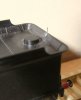
It's a smudgy looking picture from my slightly newer Olympus Camedia camera (2004), but you'll get the idea. With nowhere left to hide, the underbits got a good clean and then anything that seemed to need it was metal blacked. Not surprisingly, the water from the dehumidifier has proved far superior to our hard Mendip tap water for any cleaning. Precision Paints Two Part Primer was brush painted on - I find this an excellent product. Subsequent coats were Humbrol enamels again applied by brush. Perusal of colour photos suggested that T9s in normal service were a fairly uniform browny-black under the running plate with an oily sheen in places so the graphite top coat was let down with a mid-brown. The stainless tyres on the Romfords did not succumb to the metal black - I suppose the clue is in the name, but the AGW bogie wheel tyres were blackened, then the tyres were primed and all painted with more browny-black Humbrol goodness.
In the distant past (1990s) I was demonstrating EM Gauge chassis construction with the late Bob Alderman at Railwells. To help explain what was entailed I had come up with the bright idea of painting the compensating beams red to make them stand out. I so liked the effect that I have adopted it for all my subsequent builds. The example I was waving around that weekend was an etched brass Bulleid Light Pacific chassis with twin beams. It must have scared the living daylights out of the 'average' modeller!
Last edited:
Stevers
Western Thunderer
The AGW bogie wheels had been borrowed from another T9 build and had been knocking around for a very long time, so first job was to glue the loose tyres on. Oddly the extreme looseness of all the tyres only became apparent after painting. Not mentioned before and sitting quietly at the back, just to the right of the gearbox, is the steam reversing cylinder that in 00 Gauge can be slotted to sit on the frames and had been soldered on prior to painting. Before fitting the gearbox and pickup assembly, I put a smear of epoxy on the back of the pickups to eliminate the possibility of shorts. Loctite 243 was used on a spare Romford wheel to secure a crankpin and that was left overnight to set. In the morning I was just about able to undo the crankpin, so this medium strength retainer was used to secure the standard crankpins and the wheels were fitted. The coupling rods went on next using Rizla papers to space the crankpin washers prior to soldering them in place. A brush with a file and a dab of metal black and all looked good - and my very first standard Romford crankpins fitted - some sort of rite of passage I suppose!
 Next up was the DCC tender wiring that had been catered for with the four track PCB behind the motor. The four wires were treated as two pairs with a pair run each side of the drawbar pin. To route them conveniently these were fed into a couple of short lengths of heat shrink that I glued each side of the brake bracket under the cab. The wires were then fed up to behind the motor and shortened to a manageable length. At this point I could determine which wire needed to go where, except there was patently a short between the orange and red sockets of the DCC socket/motherboard. That shouldn't have been the case, so I released the motherboard (two screws), and yes, it did look like someone might have been there before. I ran a razor saw down the groove in the PCB between the contacts and happily the short went away. I was then able to use the wiring colours on the Zimo chip to identify what needed to go where with the multi-meter, and once the soldering was complete it moved again under its own 'steam'. Very satisfying in that Zimo chip, Hornby tender chassis, my wiring and mech were all proved to work at the same time. Next up is to solder those injectors in at the right height, put a dab of retainer on the wheel nuts and carry out the first lube with a view to fitting the bodies.
Covid precautions permitting, it will be attempting ten circuits of its home layout looking quite a lot like 30311 this week!
Covid precautions permitting, it will be attempting ten circuits of its home layout looking quite a lot like 30311 this week!
Stevers
Western Thunderer
Loose tyres and sliding out of gauge was a constant problem with Gibson plastic centre bogie and coach wheels in the 1980s.. Recent purchases have been great however.
No disrespect intended to Colin, who is one of the good guys keeping this hobby supplied. Hence my stressing the age of the wheels which pre-date Colin acquiring the AGW business and the improvements he's made to AGW product line.

At a tangent, the AGW T9 driving wheel is a superbly delicate moulding inherited by Colin that I found needed a special tool to remove successfully. This tool accepts a standard wheel puller and stops the wheel distorting by exerting force only on the hub. Worth the effort as these wheels look spectacular when fitted. They are being used on my Hornby T9 EM conversion which has a Perseverance motor pod and the lovely SEF T9 etched bogie missing from this build. My Hornby T9 is 90% complete, but was parked because there wasn't quite enough headroom for the M1220+Multibox to drive the front wheels as per this build. As a quick win it will be next up, as I now realise that I can simply replace the Multibox with the more compact RoadRunner drive and keep everything else the same.
Incidentally the Hornby T9 build also turned out to be the wrong sex when wired 'correctly'. On mentioning this on a recent visit to YMRG, I was informed that double reduction drives require the polarity of the motor feed to be reversed - obvious in hindsight!