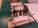
Michael,
my understanding is as follows:
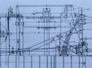
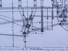
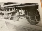
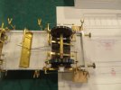
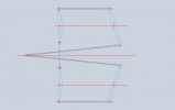
the shoes are supported vertically by means of hangers, which, with the aid of gravity, keep them aligned with a nominal height centre line of the wheel horizontally, and the tread in a plan view.
the inner shoe is also constrained in plan view because the inner end of the lever is fixed. It can only move on a rather curious 3D arc given the fixed centres of the ends of the lever and hanger. (It’s the intersection of two spheres of different radii)
the outer shoe, (right hand one in view above) is not constrained inboard-outboard, as far as I can see, however, the coning of the tyre would produce force that would tend to move it outboard when applied and this appears to be balanced by the diagonal pull of the pull rod, which, when under load, would tend to pull the inner end of the lever inwards as well as towards the brake shaft.
The linkage between the levers is pin-jointed and therefore doesn’t apply any transverse constraint, though given the inner end is fixed when under load, there will be a small resultant transverse restoring force if the outer end moves outboard.
if my breakfast-time musings are correct, the geometry shows a neat economy. I guess Mr Dean was no muppet…


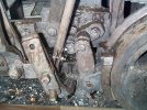
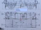
 , I totally disagree! I think the link is clear of the inward face of the cross member. The view is from above and the link is shown hidden by the items above it such as underframe, vac pipe and draw gear.