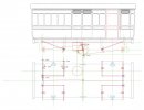
V2 4 wheel parcel van1/32 and G3

Jon Nazareth

Western Thunderer
Michael
I've always found it difficult to form the eyes on the ends of the top leaf. Your method shows a much easier way and the result looks so crisp and neat. The other item that I find a trial are the LB&SCR spring hangers but that's another story.

Jon
 

michael mott

Western Thunderer
Hi Jon, The springs brass strip from the sheet stock rather than the commercial sheared strip seems to be quite forgiving being bent. when cutting the sheet stock I use a sled on the table saw with a zero clearance and have the teeth up about double the thickness of the brass and place a sheet of waste plywood on top as a clamp. this holds everything snug and a medium slow push forward on the sled and the brass cuts very cleanly with minimal effort to clean up. The blade is 200 teeth 8 inch and .060" width.

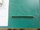
After the strips are cleaned up I used a couple of blank steel tool bits to hold the brass next to the pins and at the end that is being bent the second tool is used to bend the strip sort of like a miniature bending arm. Once the brass is like the bit in the picture I snip off the slightly longer ends to the amount needed to curl the rest of the way round the pin. I use a pair of parallel jawed pliers to do the final bend, I will post some pictures which will probably be easier to see what I am having difficulty trying to explain. This .015" brass snips easily with some flush cut side cutters, and a couple of strokes with a 320 sanding stick (I make all my own sanding sticks with ordinary sheets of wet and dry with double sided carpet tape) Most of the sticks are made with odd bits of strip wood some heavier ones with 3/4 x 1/4 and about 12" long are really handy and there is enough wood to write down the grit No on the end
 

michael mott

Western Thunderer
Pictures pictures
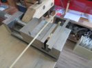
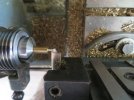
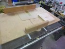
The sequence for cutting the strips this of course works for any width the key being a zero clearance between the blade and the work in this case the old sled that i have been using for years with all sorts of blades needed a new surface so a scrap of 1/8 (3mm) MDF was tacked onto the surface then the blade brought up enough to cut through.
IMG_4774x1024.jpg

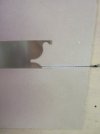
The blade is hollow ground with a flat cut. I just used a pencil to mark the successive cuts, and indexed over the brass each time.
IMG_4775x1024.jpg
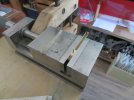
The scrap of plywood is held down with my hand to ensure the the brass doesn't move, (I keep my hand out of the blades path)
IMG_4777x1024.jpg

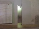
After the cut, you can see that the scrap eventually gets used enough that one need to get a new piece. they are only a venner or two deep so the wood can still be used for some other use.
IMG_4778x1024.jpg

A close up of how high the blade is.

IMG_4779x1024.jpg

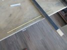
then a few strokes with the sanding stick
IMG_4780x1024.jpg

ready to start bending.

IMG_4781x1024.jpg
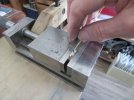
holding the strip with a bit of tool steel (anything hard would do)
IMG_4783x1024.jpg

Bringing the other bit of steel up to the pin to start bending

IMG_4784x1024.jpg

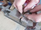
finishing leaving enough space for the side cutters to get close to snip off the excess.
IMG_4785x1024.jpg


IMG_4786x1024.jpg

I used trial and error method to guess the correct amount to leave using David Jenkinson"s Mark 1 eyeball method/
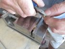
IMG_4787x1024.jpg

The ends look equal the next step is closing the loop.
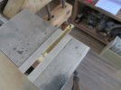
IMG_4788x1024.jpg
Using finger pressure to hold the strip in place I used the parallel pliers to close the loop.
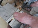
IMG_4789x1024.jpg
Gently squeezing and rotating the pliers, it is not a perfect method but works well enough for my purposes.

IMG_4790x1024.jpg

flip it end for end and repeat.

IMG_4792x1024.jpg

Ok so I have run out of space will complete in the next sequence.

Michael
 

michael mott

Western Thunderer
Continued
the loop closed
IMG_4793x1024.jpg

The final piece showing a slight difference at each end this is where the amount left after the initial bend becomes important to get right. one end just a little too short and the other a tad too long.
IMG_4794x1024.jpg

The four springs with some of the other parts.
IMG_4796x1024.jpg
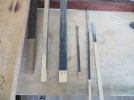
A shot of the sanding sticks i mentioned earlier.
IMG_4799x1024.jpg

the other parts of the hangers were basically eyeballed once i had made a couple following the basic dimensions.
the hole for the spring hanger being the most critical part was drilled immediately after reducing the diameter to .060"
IMG_4756x1024.jpg

next the end was radius-ed a bit
IMG_4757x1024.jpg

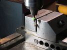
then put vertically in the bench vice to put a couple of flats onto it.
IMG_4760x1024.jpg

Then drilled, the flat was made level by balancing a short length (3") of brass to coincide with the top surface of the vice (eyeballed)

IMG_4762x1024.jpg
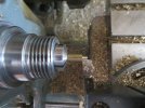
The back into the collet for the final shaping.

IMG_4763x1024.jpg

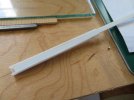
The keeper for the springs was made from some plastruct tube with 1/8th" ID first one side was planed off on the shooting board to create some square channel.

IMG_4770x1024.jpg

IMG_4771x1024.jpg

the channel was then filled with some 1/8th, by .040" strip which reduced the square tube to a rectangular one.

IMG_4772x1024.jpg

After letting the glue set overnight it was able to be sawn to length in the mitre box with the exacto saw.
IMG_4769x1024.jpg

Next I need to jig up to solder the hangers to some plates to attach to the sole bars.

Michael
 

michael mott

Western Thunderer
Moving along with the axleboxes and springs, now also the foot board hangers, these are bent up from some .032" x .062" strips and some .020"x .062" strips cut from the sheets on the table saw same method as the previous strips.
before the final work on the axleboxes.
IMG_4819x1024.jpg

adding the foot board brackets these are pushed on over the sole bars.
IMG_4831x1024.jpg


IMG_4832x1024.jpg

IMG_4833x1024.jpg

IMG_4834x1024.jpg

Michael
 

michael mott

Western Thunderer
Was a good day model wise not so good computer wise, my newer desktop windows 11 has gone snail pace a dead snail pace if there is such a speed. All the earlier photographs are on the other computer which I am taking to the repair company in the morning.

I made and fitted the keeper plates under the axle boxes, finished fabricating the foot-board hangers and finished the foot-boards on one side.

The hanger brackets are glued and pinned to the sole-boards.
IMG_4836x1024.jpg


IMG_4835x1024.jpg


IMG_4837x1024.jpg


The foot boards are made of Castello also known as Lemonwood There is a little bit of spring in the hangers.

Michael
 

michael mott

Western Thunderer
I need some help understanding the way the vacuum system worked on this van the diagrams in the carriage book are not exactly clear to me and the operation of the linkages is stumping me at the moment. If anyone can shed some light on this I would really appreciate it.
Thanks in advance.

Michael
 

michael mott

Western Thunderer
Having looked at the different images and liks withing the link that Mike shared I did not find any clear information (perhaps I missed it ) regarding the particular clasp system of braking for this van I have conjectured the system to operate in the following way

img20220813_15503258.jpg

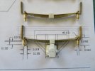
It appears to me that the main lever at the Vacuum cylinder pulls on the rods and moves through 3.78 degrees which equates to .023" in linear measurement. this pulls the bar that connects the outer shoes and at the ends move .024" (.023) because the inner shoe is connected to a similar bar that is fixed at the inside end as the outer bar pulls toward the centre moving the shoe until it begins to contact the wheel the outer end rotates toward the end of the carriage thereby pulling the inner bar toward the end of the carriage the centre of the outer bar acts a pivot, so the harder the central main bar is pulled the tighter the shoes grab the wheel.

and of course I could be completely wrong but this does make some sense to me.

I really do not like making something that I do not understand.

Michael
 

Mikemill

Western Thunderer
Michael

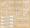
Here is an etch of brake components. The brake shoes hang down from the top of the frame they are linked by the triangular shaped irons. There are two V hangers that are positioned in the centre line of the frame, a bar goes across bottom of the V’s. On the bar are two levers, one is connected to the vacuum cylinder a second double lever sits central on the bar. There are rods that go from the ends of the double lever to the triangle irons

The system works by air pressure pushes the piston up thus pulling the first lever up and in turn the double lever rocks pulling the brakes on.

I hope this makes sense!


Mike

mt236.jpg
 

michael mott

Western Thunderer
Simon and Mike thanks for your answers, Simon your photograph confirms the basic principle of how the clasp system operates, The interesting difference between what i have drawn and your built model is that your model shows a rod to each of the outer arms whereas I connected them with a bar that is pulled by the single rod. And as the inner arms are fixed to the floor of the coach and can only rotate about the fixed point. The geometry causes the brake shoes to close.

Having the connecting bar on the outer arms in a triangular form as on the etches shown in Mike's photo makes sense from an engineering point of view as they would be much stronger.
My drawing omitted the hangers for the shoes themselves because I wanted to focus on the closure linkage.

Now I need to choose between a single triangular bar or individual rods....Hmmm

Thank you both again for your help.

Michael
 
Top