The Yard - A small industrial layout in 7mm

Greengiant

Western Thunderer
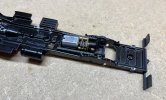
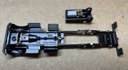
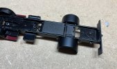
Work on the Ford Thames continues. The rear axle casting has been milled out, a test 3D print of the motor mount and axle holder was fitted to prove the concept.
 1724495761790.gif

 1724495761800.gif
From above showing slots left for mudguard mounts. When the rear bed is in place, none of this will be seen.
 1724495761809.gif
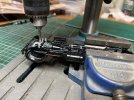
Next up was to mill out some of the original front axle mount. This was going fine until the belt snapped in the mini pillar drill.
 1724495761818.gif
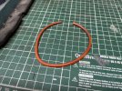
Investigation suggests the original orange belts are weld joined and not the best. I have sourced a couple of nitrile belts which are not welded and they should be here next week.
 1724495761826.gif
Martin
 

Greengiant

Western Thunderer
More work on the Ford Thames. This time removing metal to make room for the steering mechanism. The bulk was removed with a fibreglass wizzy disc.


 1724620287877.gif

The remaining stubs were removed with a Dremel bit held in a pillar drill, plus a light clean up with a file.


 1724620287885.gif

Unfortunately while gripping the vice firmly that was holding the chassis, I broke the tailboard! Easy enough to fix with some small brass angle, just annoying.


 1724620287894.gif

Then I had to get the front wheels off the axle, for this I used a back-to-back gauge to prize them off squarely with even force applied across the wheel face.


 1724620287902.gif

Once off, the main part of the stub was removed with a saw, just leaving a stub to grind off. I tried this in the lathe, but the jaws would not hold the wheel firmly and squarely enough to stop the burr pushing it into the jaws.

The solution was to clamp the wheel to a piece of MDF using four flat head screws. The MDF could be held firmly while using the pillar drill with the burr in the chuck


 1724620287910.gif

Next job is to 3D print front wheel hubs to hold the roller bearings and mount these in the wheels, then print the steering mechanism.

Martin
 

Greengiant

Western Thunderer
Currently getting ready for our next outing with the layout this Friday and Saturday at Rapido Railex in Maidstone.

Neale has done a great job converting the Ford Thames to RC, I just need to do the pretty bits, which will be an initial job that will need to be finished off fully after this weekend and before the NEC in November.

Although a big lorry, it was surprisingly awkward to get everything to fit. The battery protrudes through the existing floor, I need to make a new sub floor, which will them clamp the battery to the chassis.

 1727259195802.gif
Body off, showing the 3D printed battery holder ring and the steering servo.

 1727259195812.gif
The underside showing the 3D printed front axle assembly, the steering servo, on/off switch, battery isolation plug and socket and rear axle drive bevel gears. Still to refit is the spare wheel and carrier which goes over the rear mounting screw. We have found the tyres are not a tight fit on the wheels and come off easily! I will need to use a light smear of epoxy to hold them on.

 1727259195821.gif
I have made a start on removing the lettering using Brasso wadding. Will then buff up with T-Cut and weather.


Martin
 

Dog Star

Western Thunderer
Those tyres are uni-directional, each tread pattern ought to be fitted in the same way, ideally for forward direction of the vehicle (the driver's front wheel is correct, the vee pattern pushing water /mud away from the centre of the tyre as the wheel rotates).

Rgds, Graham
 

Osgood

Western Thunderer
Those tyres are uni-directional, each tread pattern ought to be fitted in the same way, ideally for forward direction of the vehicle (the driver's front wheel is correct, the vee pattern pushing water /mud away from the centre of the tyre as the wheel rotates).

Rgds, Graham
Correct for non-driven tyres (in this case front)?
For driven tyres I believe the passenger's side outer rear is correct?
For driven front axles it's a choice between traction and road-holding.
 

Dog Star

Western Thunderer
The tread pattern looks just like Bridgestone of the late 1970s... or maybe Firestone SAT from circa 1980 - I used both of those brands at the time.

I think that a tyre had an embossed arrow on both sidewalls arranged so that, when fitted correctly, the arrows pointed in the same direction (if you could see both sidewalls at the same instant), for example, towards the front of the vehicle.
 

Greengiant

Western Thunderer
The railway has bought its first narrow gauge steam loco, this could be an expensive mistake, early testing found it would not run on the inset track sections.

Only about 5% of the track is not inset, none of the other locos have this problem, so some head scratching occurred.
1729520664762.gif
 1729520664750.gif
On flipping the loco over it was discovered that the front re-railing bar was at an odd angle!

 1729520664762.gif
Loco has been sent to the workshops to see if a fix can be made. I suspect the bars may be removed altogether.

While there, something else needs resolving, even on the short test on the 12 inch section of normal track, the drivers could not get on with the F2 braking and the excessive inertia, this was making the controlled shunting required, very hit and miss, literally at times!

Needs to be sorted with just five weeks now until the NEC show.

Martin
 

PhilH

Western Thunderer
While there, something else needs resolving, even on the short test on the 12 inch section of normal track, the drivers could not get on with the F2 braking and the excessive inertia, this was making the controlled shunting required, very hit and miss, literally at times!
Needs to be sorted with just five weeks now until the NEC show.
Martin

Martin, Have you tried F20 - Shunting Mode ? I think this should eliminate or at least reduce the inertia.
Braking on F2 won't bring the loco to a stop unless the throttle is reduced to zero before applying F2.

On my similar loco CV3 (acceleration rate) is set at 40, CV4 (deceleration rate) is set at 110. You could set these much lower, or down to 0 should give fairly instant response to the controller.
 
Last edited:

Greengiant

Western Thunderer
Martin, Have you tried F20 - Shunting Mode ? I think this should eliminate or at least reduce the inertia.
Braking on F2 won't bring the loco to a stop unless the throttle is reduced to zero before applying F2.

On my similar loco CV3 (acceleration rate) is set at 40, CV4 (deceleration rate) is set at 110. You could set these much lower, or down to 0 should give fairly instant response to the controller.
Phil, thanks, I shall look into that. I don’t like inertia when shunting, especially when you have a target area of about 40mm for uncoupling. Makes it harder when you do the Kadee shuffle to uncouple.
Martin
 

Greengiant

Western Thunderer
 1731442105343.gif
I have at last got around to sorting out the Quarry Hunslet.

The re-railing bars have been removed.

Not a fan of the F2 braking and unworkable for shunting on The Yard.

I have done some research and found setting CV309 = 002 to 0 deactivates the brake key.

Other changes I made:

Acceleration CV3 = 44 changed to 10
Deceleration CV4 = 110 changed to 10

This makes it workable, need to try it on the layout rather than test track tomorrow and see how it behaves. Then may tweak CVs 3 and 4 to taste.

Just under two weeks until the NEC show now. The paperwork for this show has been a bundle of fun!

Martin
 

timbowales

Western Thunderer
Ah, your post gave the impression that it was the whole operating thing that was hacking you off, not just the presence of the "brake" function, not what you intended to convey perhaps?
 
Top