Stevers
Western Thunderer
This is the place where I will try to (or more likely won't) complete my many unfinished projects.
First up is a Hornby Van C that once graced Beaminster Road and was a gift from Tim. A 'simple' EM conversion (I thought) to make another 'Adaptavan', in this case to go between locos with 'three link' and coaches with Kadee couplings. My locos always have hooks and chains, and may also have a Kadee on the tender. Coaches may be ELC(N Gauge) on wires or Kadees, and may also have hooks if non-corridor. The goods stock that was set up for Mere has Kadees, unless they've fallen off, otherwise three link. For Verwood I need to be able to drop off and collect goods stock, and although Kadees could do that, it doesn't seem quite right for a UK steam era layout, but that's a decision for further down the line.
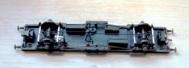
To remove body from underframe was just a matter of releasing the six clips underneath and easing the body off whilst making sure that the vacuum pipes were released at each end. The wheels could be released by unclipping the retainers from the top and releasing the long plastic brake rodding that was much more robust than it looked and came to no harm. I found a pair of EM bogie/tender wheel axles, that must have been left over from the Wills T9 in 00 that I finished for Tim, and I fitted a couple of 00/EM coach wheels to them. I replaced the retainers after snipping off the fragile looking brake gear. The weighted underframe ran through my test crossover very smoothly indeed - so far so easy.
I needed to spread and refit the brake blocks, and over engineering these started with an oblong of .040" styrene 10mm x 8mm. An 8mm x 5mm spacer was placed in the middle of the front and then a 20mm x 3mm strip at the back. This gave me two 'Ls' at the correct spacing to take the Hornby brake shoes and their crooked mounts. The Hornby plastic definitely takes solvent, but I still used two 3mm x 4mm blocks to wedge the crooked arms in place. The two areas not covered by all these bits of styrene were cut out to clear the wheels. I tried a test fit, and the units sat too low, so I added a further 20mm x 8mm piece (020") to pack them up to about the right height. There was too much side play in the EM wheel sets so instead of adding tubes/washers in the middle I put some .010" ABS strips on the inside of the Hornby W irons to limit travel so that the brake blocks at the correct spacing wouldn't rub on the flanges.
How to restore the brake stretchers? Having considered my options I elected to fret some out of 015" nickel silver, filing in the little divots at the ends that locate in the brake block holes. I had bought a gross of fret saw blades at an unfeasibly low price - and you could tell, as it was impossible to keep them on track and they won't cut steel. I then soldered some short lengths of wire onto the stretchers to represent the pull rods. These were then glued in place and the complete assemblies installed in the underframe as close to the wheels as I dared. So far not nearly so easy.
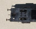
To be an 'Adaptavan' it needed a hook (preferably sprung), and surprisingly there was no representation of the hook at either end let alone any sort of slot. The only way forward was to file about 015" off the central panel of the buffer beam, and I then drilled a hole through to the void under the NEM coupling mount. Surprisingly I was able to open this hole out to 1/8" to take a coupling hook spring. I then put a slot into a piece of 015" nickel silver for the coupling hook then trimmed it to fit my central panel and epoxied it on with the spring already inserted. Once the glue had set, I was able to insert the hook, compress the spring and pop a bent piece of wire in the hole to retain the hook. Drilling the hole destroyed the Hornby plastic buffer springs, so these were substituted with strips of brass folded at the end to thicken them up so that they better fitted the slot where they were epoxied in. The buffers do still spring, but perhaps not quite as well as they did. How easy? The less said the better!
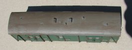
Being a Chinesium Hornby Maunsell vehicle it had lost a couple of what look more like moulded in torpedo roof vents. I looked at my collection of brass and white metal torpedo vents, but as they were a poor match for the surviving ones, I ordered some 3D printed 'LNER style' ones that seem to be a better match, and I'll probably replace all five, keeping the surviving Hornby ones as spares for my Maunsell pull-push unit and 2-set.
First up is a Hornby Van C that once graced Beaminster Road and was a gift from Tim. A 'simple' EM conversion (I thought) to make another 'Adaptavan', in this case to go between locos with 'three link' and coaches with Kadee couplings. My locos always have hooks and chains, and may also have a Kadee on the tender. Coaches may be ELC(N Gauge) on wires or Kadees, and may also have hooks if non-corridor. The goods stock that was set up for Mere has Kadees, unless they've fallen off, otherwise three link. For Verwood I need to be able to drop off and collect goods stock, and although Kadees could do that, it doesn't seem quite right for a UK steam era layout, but that's a decision for further down the line.
To remove body from underframe was just a matter of releasing the six clips underneath and easing the body off whilst making sure that the vacuum pipes were released at each end. The wheels could be released by unclipping the retainers from the top and releasing the long plastic brake rodding that was much more robust than it looked and came to no harm. I found a pair of EM bogie/tender wheel axles, that must have been left over from the Wills T9 in 00 that I finished for Tim, and I fitted a couple of 00/EM coach wheels to them. I replaced the retainers after snipping off the fragile looking brake gear. The weighted underframe ran through my test crossover very smoothly indeed - so far so easy.
I needed to spread and refit the brake blocks, and over engineering these started with an oblong of .040" styrene 10mm x 8mm. An 8mm x 5mm spacer was placed in the middle of the front and then a 20mm x 3mm strip at the back. This gave me two 'Ls' at the correct spacing to take the Hornby brake shoes and their crooked mounts. The Hornby plastic definitely takes solvent, but I still used two 3mm x 4mm blocks to wedge the crooked arms in place. The two areas not covered by all these bits of styrene were cut out to clear the wheels. I tried a test fit, and the units sat too low, so I added a further 20mm x 8mm piece (020") to pack them up to about the right height. There was too much side play in the EM wheel sets so instead of adding tubes/washers in the middle I put some .010" ABS strips on the inside of the Hornby W irons to limit travel so that the brake blocks at the correct spacing wouldn't rub on the flanges.
How to restore the brake stretchers? Having considered my options I elected to fret some out of 015" nickel silver, filing in the little divots at the ends that locate in the brake block holes. I had bought a gross of fret saw blades at an unfeasibly low price - and you could tell, as it was impossible to keep them on track and they won't cut steel. I then soldered some short lengths of wire onto the stretchers to represent the pull rods. These were then glued in place and the complete assemblies installed in the underframe as close to the wheels as I dared. So far not nearly so easy.
To be an 'Adaptavan' it needed a hook (preferably sprung), and surprisingly there was no representation of the hook at either end let alone any sort of slot. The only way forward was to file about 015" off the central panel of the buffer beam, and I then drilled a hole through to the void under the NEM coupling mount. Surprisingly I was able to open this hole out to 1/8" to take a coupling hook spring. I then put a slot into a piece of 015" nickel silver for the coupling hook then trimmed it to fit my central panel and epoxied it on with the spring already inserted. Once the glue had set, I was able to insert the hook, compress the spring and pop a bent piece of wire in the hole to retain the hook. Drilling the hole destroyed the Hornby plastic buffer springs, so these were substituted with strips of brass folded at the end to thicken them up so that they better fitted the slot where they were epoxied in. The buffers do still spring, but perhaps not quite as well as they did. How easy? The less said the better!
Being a Chinesium Hornby Maunsell vehicle it had lost a couple of what look more like moulded in torpedo roof vents. I looked at my collection of brass and white metal torpedo vents, but as they were a poor match for the surviving ones, I ordered some 3D printed 'LNER style' ones that seem to be a better match, and I'll probably replace all five, keeping the surviving Hornby ones as spares for my Maunsell pull-push unit and 2-set.
Last edited: