Sieg SX3 Mini Lathe improvements adventure

Rob Pulham

Western Thunderer
Carrying on the discussion above, lack of space didn't allow me the option of a Myford or any other "bigger" lathe. I wasn't really looking for another/bigger lathe, as happens in life, I saw this one for sale at sensible money and decided to investigate what I was potentially getting.

This particular lathe was in fact advertised as a C3 rather than and SC3 so initially I was investigating the pros/cons of C3's. The principle differences seem to be that the C3 has a 350 watt brushed motor with 2 speed ranges changed by a lever on the back of the machine. Whereas the SC3 has a 500 watt brushless motor variable speed by direct drive. There are other more cosmetic differences as mentioned in my last post and variants of the C3 are still still sold under lost of brand names some by resellers like Vevor at under £500 for a compete bundle of stuff.

During the course of dialogue with Martin I started to realise by looking closely at the sales photos that the machine I was considering was in fact the more recent SC3 with the 500 wat brushless motor. Having looked closely at what I might potentially need/desire to do to make the machine more versatile I went ahead and bought it.

Just picking up on Martin's point about none of these upgrades are essential. I turned some really nice small fittings for the Stanier tender without any kind of issues and I am sure that I could do similar with aluminium. However when you come to harder materials like steel/stainless the lack of rigidity is more apparent. From the outset I decided that I would carry out the improvements that I had seen other people do while researching whether to buy it or not in order to gain a bit more intimate knowledge of the lathe and a bit more practice at machining.
 

OzzyO

Western Thunderer
Carrying on the discussion above, lack of space didn't allow me the option of a Myford or any other "bigger" lathe. I wasn't really looking for another/bigger lathe, as happens in life, I saw this one for sale at sensible money and decided to investigate what I was potentially getting.

This particular lathe was in fact advertised as a C3 rather than and SC3 so initially I was investigating the pros/cons of C3's. The principle differences seem to be that the C3 has a 350 watt brushed motor with 2 speed ranges changed by a lever on the back of the machine. Whereas the SC3 has a 500 watt brushless motor variable speed by direct drive. There are other more cosmetic differences as mentioned in my last post and variants of the C3 are still still sold under lost of brand names some by resellers like Vevor at under £500 for a compete bundle of stuff.

During the course of dialogue with Martin I started to realise by looking closely at the sales photos that the machine I was considering was in fact the more recent SC3 with the 500 wat brushless motor. Having looked closely at what I might potentially need/desire to do to make the machine more versatile I went ahead and bought it.

Just picking up on Martin's point about none of these upgrades are essential. I turned some really nice small fittings for the Stanier tender without any kind of issues and I am sure that I could do similar with aluminium. However when you come to harder materials like steel/stainless the lack of rigidity is more apparent. From the outset I decided that I would carry out the improvements that I had seen other people do while researching whether to buy it or not in order to gain a bit more intimate knowledge of the lathe and a bit more practice at machining.

Hello Rob,

one set of parts that I would suggest to get for your lathe is a collet holder and a set of ER collets to go with it.

ATB

OzzyO.
 

Rob Pulham

Western Thunderer
Hello Rob,

one set of parts that I would suggest to get for your lathe is a collet holder and a set of ER collets to go with it.

ATB

OzzyO.
Thanks Paul,

You are not the only one to recommend them and I have a set that work for both lathe and mill.
 

Rob Pulham

Western Thunderer
Although I have been waiting for delivery of various bits of metal and fixings which slowly trickled in over the new year (I have everything I need now, I think or should that be hope). I haven't been idle.

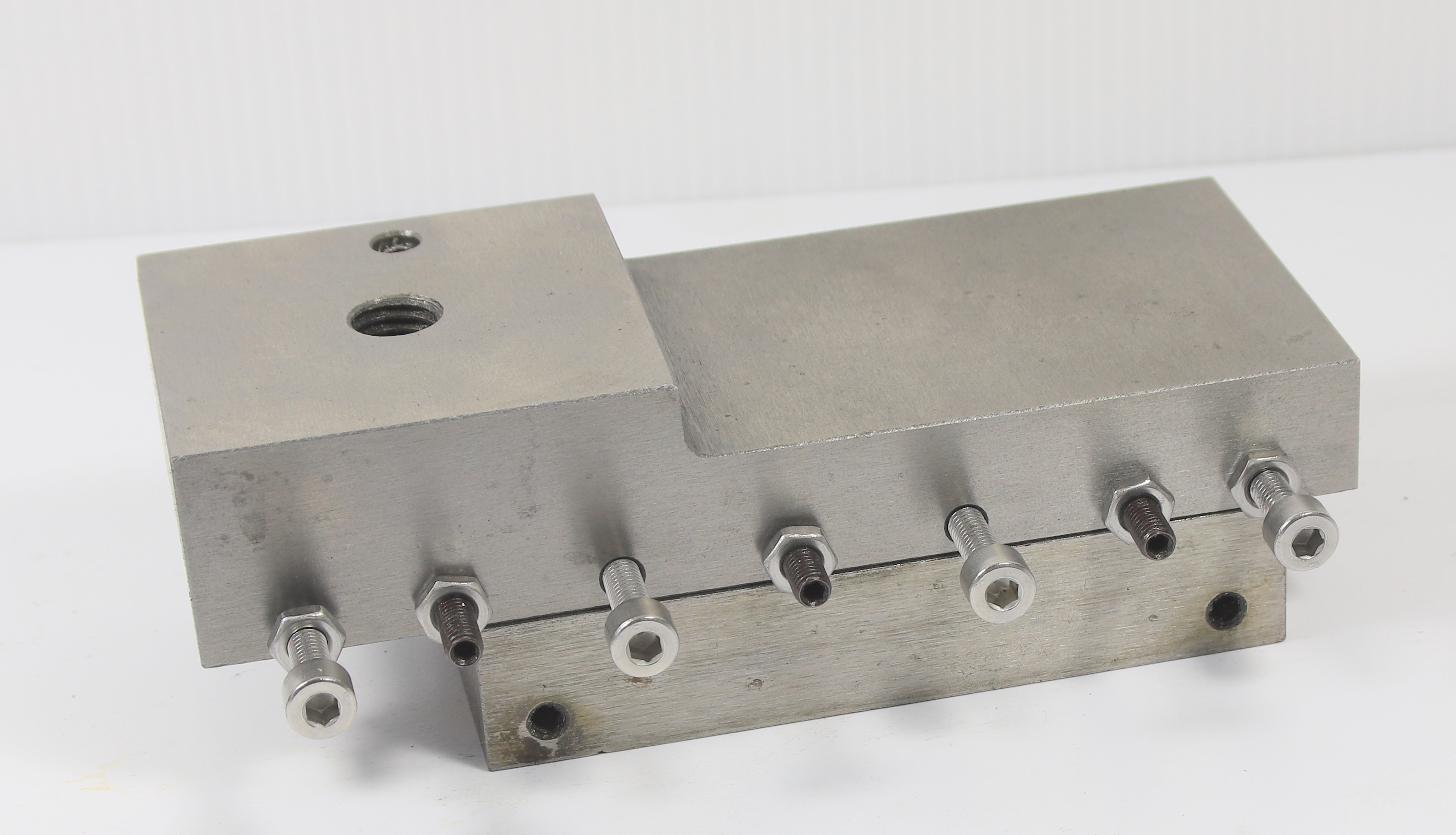
I got the stainless steel lock nuts for tensioning the Gibs on the two slides and managed to get those ready to refit.

51808513007_894dbb674b_o.jpg


51810205530_024103183b_o.jpg


51809470066_a23dbb1174_o.jpg


51810192455_8759077de6_o.jpg


51809570678_58b3cda9bf_o.jpg


The last photos also show an anti backlash nut/block which I hope will take out the backlash from the cross slide lead screw. It's an idea I got from the US YouTuber that I mentioned (username of Dr Jim) who made his from oil impregnated bearing bronze. I looked into getting some and nearly had a heart attack so settled for testing the concept in acrylic as I had seen another person do who had fitted anti backlash blocks to a home made CNC Mill.

Whilst making the anti backlash nut/block was quite simple. Finding out the thread size/pitch was a bit of a challenge and I am grateful to members of the Model Engineer forum who between a few relies gave me the information that I needed to work it out.

Why was it so difficult you might ask. Well, I have previously mentioned that the machine is imperial but fitted with Digital Read Outs on the cross slide. From what I have read, when fitting the DRO kit's the lead screw is replaced as part of the upgrade. I rang Chronos who are the supplier of DRO kits in the UK who told me that the lead screws included in the kits are metric. On this basis it seemed logical that the cross slide leadscrew may in fact be metric.

As you might imagine a query on the ME forum elicited quite a few helpful answers and a few less than helpful ones thrown in for good measure. Ultimately I was pointed in the direct of a US site and advised that some of the machines actually came factory fitted with DRO's and they retained imperial lead screws. With the help of replies that were specific with information I finally worked out that my cross slide leadscrew is a left hand thread 3/8" 20TPI. Part of my difficulty was that I had no idea of how BSF threads were actually measured as I have never had cause to buy or measure any BSF fixings. All my experience has been in Metric or for modelling purposes, BA screws etc. Where we specify the whole thread length.

A set of taps was duly ordered from RDG engineering supplies (£10.96 inc. postage) and the job was done.
 

mike evans

Active Member
Although I have been waiting for delivery of various bits of metal and fixings which slowly trickled in over the new year (I have everything I need now, I think or should that be hope). I haven't been idle.

I got the stainless steel lock nuts for tensioning the Gibs on the two slides and managed to get those ready to refit.

51808513007_894dbb674b_o.jpg


51810205530_024103183b_o.jpg


51809470066_a23dbb1174_o.jpg


51810192455_8759077de6_o.jpg


51809570678_58b3cda9bf_o.jpg


The last photos also show an anti backlash nut/block which I hope will take out the backlash from the cross slide lead screw. It's an idea I got from the US YouTuber that I mentioned (username of Dr Jim) who made his from oil impregnated bearing bronze. I looked into getting some and nearly had a heart attack so settled for testing the concept in acrylic as I had seen another person do who had fitted anti backlash blocks to a home made CNC Mill.

Whilst making the anti backlash nut/block was quite simple. Finding out the thread size/pitch was a bit of a challenge and I am grateful to members of the Model Engineer forum who between a few relies gave me the information that I needed to work it out.

Why was it so difficult you might ask. Well, I have previously mentioned that the machine is imperial but fitted with Digital Read Outs on the cross slide. From what I have read, when fitting the DRO kit's the lead screw is replaced as part of the upgrade. I rang Chronos who are the supplier of DRO kits in the UK who told me that the lead screws included in the kits are metric. On this basis it seemed logical that the cross slide leadscrew may in fact be metric.

As you might imagine a query on the ME forum elicited quite a few helpful answers and a few less than helpful ones thrown in for good measure. Ultimately I was pointed in the direct of a US site and advised that some of the machines actually came factory fitted with DRO's and they retained imperial lead screws. With the help of replies that were specific with information I finally worked out that my cross slide leadscrew is a left hand thread 3/8" 20TPI. Part of my difficulty was that I had no idea of how BSF threads were actually measured as I have never had cause to buy or measure any BSF fixings. All my experience has been in Metric or for modelling purposes, BA screws etc. Where we specify the whole thread length.

A set of taps was duly ordered from RDG engineering supplies (£10.96 inc. postage) and the job was done.
Morning Rob
When a DRO is fitted to lathe or milling machine then backlash is of no consequence. The DRO only reads movement, in other words it reads movement after the backlash is taken up.

Mike
 

JimG

Western Thunderer
When a DRO is fitted to lathe or milling machine then backlash is of no consequence. The DRO only reads movement, in other words it reads movement after the backlash is taken up.

I think the DROs on Rob's lathe are driven from the leadscrews of the crosslide and topslide, so won't take account of backlash on these screws.

Jim.
 

Rob Pulham

Western Thunderer
Thanks Mike,

There was quite a bit of discussion on the subject on the ME forum and the conclusion was as Jim suggests, that the type of DRO's fitted don't eliminate backlash. So I decided while I had it in bits to do what I can to mitigate it. Time will tell as to whether I have succeeded. In any event I have learned much from the exercise so it's not a complete waste.
 

Rob Pulham

Western Thunderer
Much of the following few days was spent squaring up pieces of stock and removing the mill scale that is present on the hot rolled steel that I am using for many of the parts. It was during this process that I had my first go at fly cutting. - Subsequent to posting this on the GOG forum, I was pointed at "Noggin End Metals" for obtaining free machining steel so I will look there for materials for future projects.

It was a bit scary at first, mainly because my fly cutter is very lightweight and was bought with a view to cutting chimney flares on the Unimat.

This meant that I had to play around quite a bit to find the best speed/feed rates. At one point I knocked a small chip out of the cutter so I had to regrind it. I had read somewhere that fly cutters work better when there is a small radius on the end of the tool so as I reground it, I added one and it did make a difference.

At some point I will invest in, or make a heavier duty Fly Cutter Arbor.


mike evans

Active Member
I think the DROs on Rob's lathe are driven from the leadscrews of the crosslide and topslide, so won't take account of backlash on these screws.

Jim.
Hello Jim
I was not aware that the Seig DRO worked off the lead screw and now understand why Rob needs to eleviate back lash.
Looking at fitting instructions, back lash has to be taken out and then the DRO is set to zero. Unless Rob removes 100% of the back lash then the DRO has to be set to zero every time.
If the carriage is moved, say, 100 thou but the carriage is moved too far and needs to be moved back, then any back lash, however small, needs removing and the DRO set to zero.
This seems a recipe for disaster and errors easily made.
Personally, I think you should splash the cash and buy a linear DRO which will take away the back lash problem
Mike
 

simond

Western Thunderer
Or just always go the same way. If you advance by some dimension and overshoot, wind back by more than you overshot, and then advance to the dimension again, it should be correct.

Of course, having a leadscrew with negligible backlash, or a DRO that reads the actual position, would be easier.
 

michael080

Western Thunderer
All that has been written about backlash is very true, but don't forget that not only the dial has a backlash but also the carriage.
As an example, if you want to plain turn an outer diameter, you have to approach the correct dimension coming from a bigger diameter. If you set your dimension from smaller diameters, the carriage will be pushed back as soon as the cutter touches the rod.
So I think it is always a good idea to have a possibility to minimize backlash.

Michael
 

Rob Pulham

Western Thunderer
Thanks Gents,

While I understand where Mike is coming from, in reality on this lathe at least there was no backlash in the compound slide and very little in the cross slide and that I hope to have eliminated with the backlash nut. Prior to stripping it down I was able to turn several identical brass fittings using the DRO so they should be adequate for modelling purposes going forward but if I have issues then I will consider a linear scaled type (fitting one to my Mill is more of a priority at the minute though.

Michael, I take your point about the carriage, one of the improvements that I am working on is a carriage lock for that very purpose.
 

OzzyO

Western Thunderer
Hello all,

in one of my past lives I worked on a milling machine (M/C) Parkson M1700 if you want to look it up. This had a backlash eliminator in the form of a half nut, this was nothing to do with the indexing it was so you could "climb mill" (that is cutting from right to left with the cutter at the back of the job). If you cut like that on a normal lead screw the cutter will try and pull the job in (through).

A lead screw is like any other screw in that it has to have some play for it to work, all screws work the same. If your cutting out a square hole on a mill, and you start at the right corner with the cross slide wound in and zero the index, then advance to the L/H corner on the longitudinal travel when you get to the length you want set the index to zero, bring the cross slide to you, until you get to the size you want (make a note of the index). Advance to the R/H corner minus the backlash ( 0 in one direction + or - 25 thou in the other) then back to your first zero, This will work for all of the holes that you want to cut out as long as keep to the same directions of cutting.

The same will work on a lathe cut the outside dia. drill the hole bore the hole to the size you want, make a note of your indexes and repeat as much as you want. This will only work as log as you have a multposition tool post or a quick change one.

OzzyO.
 

Rob Pulham

Western Thunderer
Next comes the most daunting part so far, machining the carriage casting to square up the cut outs in each side to take the extension pieces which will support the carriage stop.

Being a casting, the very nature of it is rounded corners and rough finish. At the very least the faces needed flattening to take the machined block which is to be let into each cut out. As I was studying the cut outs to determine how best to machine them, I noted that at the side where the inverted V was machined into the base there was a distinct slope to the edge of the cut out.


When I check this with a protractor it was almost 80 degrees. There wasn’t enough casting left to make this edge vertical without cutting into the inverted V so it made sense to machine this edge to 80 degrees. I reasoned that cutting the opposite edge to the same angle would also help relive any potential stresses on the M6 screws that I plan use to fasten these infill blocks to the carriage, when the lock is tightened down.


I then machined the ends of the infill blocks to suit the angled cut outs.


All this was made less stressful by the knowledge that a replacement carriage casting is only £23 plus P&P.
 

michael080

Western Thunderer
That appears to be a tricky operation. Removing the casting skin might warp the casted part resulting in a slight banana shape of the whole thing. That could be a problem for the parallel guideways. All that could be compensated by reshaping the guideways....
Btw., how is the infill block fixed?
Michael
 

Rob Pulham

Western Thunderer
Good morning Michael,

Thankfully none of what I am doing is ground breaking, in so much as I am copying what others have done before and I haven't seen any reports of issues of the casting warping after being squared up.

That isn't to say that there can't be a first time of course... But having tried them on the ways several times to take measurements I can't feel any sign of rocking etc. so far.

Your question on how the infill block is fixed is very timely.

The first bit of the carriage work is now complete and I am happy with how it's gone so far.

51815040062_372ca44f0d_h.jpg


Next more character building work with a hack saw...
 

Brian McKenzie

Western Thunderer
. . . . I haven't seen any reports of issues of the casting warping
Neat work with the addition of those side blocks Rob, but don't crank down the midpoint screws too hard when locking the carriage - you may find the cross-slide movement start to stiffen up in the V-ways.

When everything is re-assembled, I'd be interested to learn if you can detect this effect.

-Brian
 

Rob Pulham

Western Thunderer
Hi Brian,

The plan is that I only need to tighten the right hand one to lock the carriage. The guy whose idea I am using, only needs to turn his a quarter turn to lock the carriage and I hope for something similar.
 

mickoo

Western Thunderer
This is all very good but why are you adding a second carriage lock when you already have one on the feed screw?

There should be a lever on the back to disengage the feed screw and you can then use the lock to secure the carriage. I have no need for the feed screw so that was the first thing I did, if I do need it then I just re-engage the gear.
 
Top