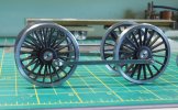
Scratch build - LNWR Precursor Tank - Scale7

Ian@StEnochs

Western Thunderer
Thanks for the advice - no doubt I'll repeat the same mistakes so I'll build in the option to add springing if required. My favoured springing is the continuous springy beams so it will need a little thought and option to alter it to get the balance right.

Any advice or recommendations for the rear carrying wheel? It was a radial axlebox so I'm still deliberating on how to make it and retain some easy springing.

Adrian,

So far I haven’t tackled an Atlantic but I have built quite a few 0-4-2s and 0-6-2 tanks. None of the originals had radial axle boxes so I have no experience of them.

In all my locos I have arranged the trailing axle in conventional axle boxes individually sprung, as is my preference, and given them as much side play as possible. So that pickups don’t restrict the side play I use floating plungers or split axles on the trailing wheel set. The setup works fine and running is all I expect.

Ian.
 

Yorkshire Dave

Western Thunderer
Any advice or recommendations for the rear carrying wheel? It was a radial axlebox so I'm still deliberating on how to make it and retain some easy springing.

Many moons ago I built a Roxey LBSC E4 0-6-2T which has a rear radial axlebox/truck. Instead using the radial box sides supplied in the kit I used double-sided thin PCB so I could utilise a split axle pick up. I'll try and dig out some photos so see how I sprung the radial box for track holding.
 

adrian

Flying Squad
In all my locos I have arranged the trailing axle in conventional axle boxes individually sprung, as is my preference, and given them as much side play as possible. So that pickups don’t restrict the side play I use floating plungers or split axles on the trailing wheel set. The setup works fine and running is all I expect.
Thanks for the info - I'm still working out the details in my head for the trailing axle. I might do the same as it suits my preference for continuous springy beams.

Prior to that I've started the main coupling rods. Being 4-coupled nothing too complicated, however I have a preference for steel motion and correct fluting, hence the following.

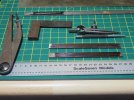
Starting with a couple of lengths of steel bar stock. First using the odd-legs to find the center-line, guesstimate the setting and draw a short line from one side of the bar side, then flip them over to the other side. If the marked line doesn't match from the other side then the spacing needs adjusting. The square and rule is then used to mark out the 10ft spacing, the centres are then marked with the center-punch. and the boss diameters marked with the dividers.

precursor-coupling-rods-1 - 1.jpeg

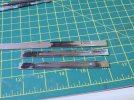
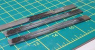
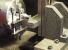
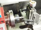
The fluting is done with a woodruff cutter in the lathe and the steel bar clamped to a vertical slide on the lathe carriage. The top bar is just a test piece to check I have the correct depth settings on the cut. This gives the correct flare out at the ends of the fluting, something that can't be done with using and end mill, nor with etched rods without a lot more work.

precursor-coupling-rods-1 - 2.jpeg

Care needs to be taken to take the flare up to the edge of the boss marked out.

precursor-coupling-rods-1 - 3.jpeg

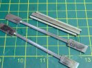
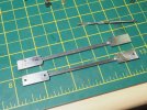
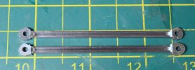
Before thinning the depth of the rods on the fluted section I cut out the centre section using a piercing saw. As mentioned elsewhere it's not difficult to follow the line with the piercing saw. The trick I use - don't force the saw in to the cut, let the blade do the cutting, my action on the saw is just up and down and steer, let the blade cut at the rate it can. Keeping the blade truly vertical is the problem for me, this can be seen in this photo at the lefthand side of the rods. About 25% from the lefthand side you can see a step change in the vertical draft of the cut, this is where the cut from one side met the cut from the other side, it will file out on the final finish of the rods. The sections cutout will be kept as there is a chance they can be recycled for making the crosshead slide bars.

precursor-coupling-rods-1 - 4.jpeg
 

Rob Pulham

Western Thunderer
Hi Adrian,

A couple of questions if I may.

What are the dimensions of the bar that you using to create the rods from?

What size is your woodruff cutter?
 

Richard Gawler

Western Thunderer
The fluting is done with a woodruff cutter in the lathe and the steel bar clamped to a vertical slide on the lathe carriage.
Please Adrian - if I am am reading this correctly: the work is clamped in the horizontal plane and oriented along the axis of the cross slide. The vertical slide is lifting the work to engage the cutter, and the cross slide is then moving the work along to let the cutter make the slot. So, the lathe centre has sufficient space above the cross slide to install the vertical slide, and then I guess clamp a 90 degree angle onto the vertical slide to hold the work? A photo would help but I expect you have dismantled everything :)
 

bambuko

Western Thunderer
Has been described here on the forum before:
You can also see it on the blog here:
and a pic:
coupling_rods-5.jpg
 

adrian

Flying Squad
Hi Adrian,

A couple of questions if I may.

What are the dimensions of the bar that you using to create the rods from?

What size is your woodruff cutter?
I can't remember off the top of my head and I'm away from home at the moment - I'll let you know later in the week when I get back.
 

OzzyO

Western Thunderer
Hello Adrian,

as you set up the vertical slid for the fluting why not cut out the stepped parts of the rods as well?

ATB

OzzyO.
 

adrian

Flying Squad
You can also see it on the blog here:
Thanks for posting that link for me! The setup is the same but this time the sequence is slightly different, I decided to do the fluting on the rods first prior to thinning the section. Thinning the section isn't critical on alignment so I've setup to do the fluting first which made it easier to check that the coupling rod is aligned correctly with the cross slide. I did also find that I had to adjust the position of the vertical slide on the cross-slide as the scale 10' rods are close to the limit of travel of the cross slide.
 

adrian

Flying Squad
Hello Adrian,

as you set up the vertical slid for the fluting why not cut out the stepped parts of the rods as well?

ATB

OzzyO.
Simply it was quicker and easier to cut out by hand.

The machine vice I have for the vertical slide doesn't have wide enough jaws to clamp the full length of the rods. So I'd have to rig alternative clamping along the length and sorting out the alignment isn't easy in the lathe as there too much "infrastructure" in the way to get a clear view of work piece. Whilst I'm happy to do "horizontal" milling in the lathe I've never been that keen on using it for "vertical" milling operations.

The coupling rods have a subtle fish-belly shape to them so needed to be finished by hand anyway.
 

adrian

Flying Squad
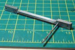
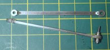
The next step was to drill the crankpin hole, a 4-coupled is nice and easy as no joints to mess around with. The exact spacing (scale 10') isn't too critical as I'll use them as jigs when fitting the hornblock guides, what is critical is that the spacing is identical on the 2 rods. So the two right hand bosses have beend drilled and reamed for the crankpin bush, only one lefthand boss has been drilled (not reamed).precursor-coupling-rods-2 - 1.jpeg

I line the two rods up using either the reamer shank or a length of silver steel rod through the reamed bosses, clamp the two together and drill the final boss. After which the remaining two holes can be reamed.

precursor-coupling-rods-2 - 2.jpeg

Now that is sorted - return to the vertical slide in the lathe to thin down the section between the bosses front and rear. I did the front side first and then turned them over to take a skim off the rear. A strip of shim is required underneath when doing the rear to ensure it is supported along the length.

precursor-coupling-rods-2 - 3.jpeg

It's then a case of final rough cutting out of the rods.

precursor-coupling-rods-2 - 4.jpeg

In the past I have made a little filing button to located on the boss when filing the bosses circular, however on this occasion I realised then I had a miniature ball race of the correct diameter so I made a little bush so I could bolt it in place. The bosses could be then filed to shape using a set of needle files.
precursor-coupling-rods-2 - 5.jpeg
precursor-coupling-rods-2 - 6.jpeg

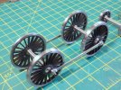
A quick setup check with the wheels to gauge the finish and spacing. The oiling boxes will be added later to finish them off but this is all that is required to make a start on the main chassis frames.
precursor-coupling-rods-2 - 7.jpeg
precursor-coupling-rods-2 - 8.jpeg
 

adrian

Flying Squad
Usual problem of work pressures at the moment but I have spent a little time progressing the build. The frame drawings were finished by sketching them out over the GA drawing so I could then draw them out on the nickel-silver sheet. Nothing more complicated than a scriber, steel rule, odd-legs, dividers, square and a centre punch.

Now I could be rather smug and claim that it's a prototypical build because the looking at the GA drawing the frames appear to be built up from three distinct pieces. There is a central section with the main driving wheel hornblocks, then the front frames over the bogie are rivetted inside (so slightly narrower) the main frame. Likewise with an extra spacer the rear frame under the coal bunker is a another section. So I have drawn up the frames in 3 pieces.

However the reality is that it's a very long frame and I simply didn't have a sheet of nickel-silver of sufficient size to cut it out in one piece. I did have a couple of shorter 22' n/s sheets so cutting out the 3 sections was the expedient solution. The two sheets were soldered together, one edge was then filed straight and level to use as a reference line for marking out. These were then cut out with the piercing saw and then filed to the marked lines. Nothing at all complicated.
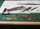
precursor-frame - 1.jpeg

In discussion with modellers about scratch building and cutting out to shape one thing that crops up is the ability to file a sheet of metal to the marked line. Once again it really isn't a special skill - it's simply practice with the tools you have. I really do think anyone can achieve this if they give it a go.

It's difficult to explain in words, sometimes the exhibition workbenches are the place to learn from those with the skill. I spent hours as a teenager pestering Tony Reynalds at a Bristol exhibition one year on his methods. Absolutely brilliant engineer and spent all the time in the world taking me through what he was doing. So in a similar vein a small dive into workshop techniques, last year I bought a macro lens hence I have managed to get a couple of photos to illustrate the point.

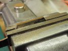
This is simply nothing more mundane than filing a sheet of metal to a marked line. Just a straight line marked on a bit of metal, if I remember correctly the bit in the photo is the front frame section by the bogie. Pick the biggest file possible, a second cut or smooth 6" at least in 7mm scale. The larger the file the easier it is control and keep straight and level - this is not a job for needle files! Personally I have my workbench at a fairly high level so for jobs like this I can be standing up in a comfortable position when filing to shape.

As I file down the sheet to the marked line I frequently take the material out to see which side needs a little more effort and how close to the marked line I am. The trick to note and the purpose of the following photos is to illustrate what happens when you get to the line so if you try something similar you can recognise it. When you mark out the shape for the component (the frame in this case) you place a small score in the metal, as you file down to that line if you are observant you can see a small sliver of metal peel off. In the photo below you can just see on the right hand side of the flat I'm filing a faint "thread" of metal as it seperates from the main sheet. This is a clear indication that I have reached the line on that side of the component.
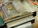
precursor-frame - 2.jpeg

So now I know I have reached the mark on the right hand side so more filing has concentrated over to the lefthand side. As shown in the photo below this "thread" of metal has now separated along the length. This shows that I have reached the marked line along the length.
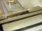
precursor-frame - 3.jpeg

When I get to the end and the final bit separates and I end up with a curl of metal from the metal sheet. This is a good indication that I've filed to the marked line and a quick draw filing along the sheets gives a final polish and removes most to the file marks.

p.s. this is another good reason for using nickel silver sheet for scratch-building. This "line peel" is a lot harder to recognise with brass sheet.
precursor-frame - 4.jpeg

Now I'm drawing up frame spacers which is entertaining and plotting a "novel" arrangement for the rear radial truck - I'll have to see how that works out!

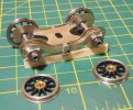
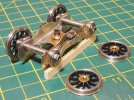
To follow up with a quick response to previous questions - another couple of photos to illustrate the front bogie arrangement to show the miniature ball races.
precursor-frame - 5.jpeg

In addition to the dummy springs on the compensation beam the arrangement on this loco has a series of "cross-members" between the horn-guides. So on the the bogie below there is a securing bolt across the bottom of the horn-guide to retain the horn-block, which is the 14BA bolt in the photo - I still have to make a tube and cross-member to thread through this bolt and it acts as a tie-bar to the horn-guide on the other side. The main frames are also scant on frame spacers and also have a similar tie-bar arrangement between the horn-guides!
precursor-frame - 6.jpeg
 
Last edited:

michael mott

Western Thunderer
Also Watching. Funny that I picked up my own loco today then spotted this thread.
Adrian thanks for your many photos and commentary on this build I'm still getting my head wrapped around how much smaller this is than my P2 because your photos make it appear to be larger than my own 1/32nd scale bogie. The use of the woodruff cutter on the lathe is a nice touch.
I like the wire springs too.

Michael
 

adrian

Flying Squad
Good to see fellow FreeCAD user :thumbs:
I have never used the drawing workbench (too clunky for my liking) but I see it serves you well?
Yes I'm learning FreeCAD principally for building some 3D components and have been trying the drawing workbench. It works okay and I found my way around it.

However I'm long time user of QCAD so I'm flip flopping between the 2 at the moment according to needs. I think my process is going to be use QCAD for 2D drawings and then import the files into FreeCAD for conversion into 3D models where appropriate.
One question, please if you don't mind:
what is the bearing (size or part number?) that you use in the front bogie?

They are the imperial FR156ZZ - 3/16x5/16x1/8 so they fit on the standard Slaters axle.

I find this thread very informative - would almost be worth converting it into e-book for education of the masses :D
Thanks - I'm still exploring various options for something along those lines - another item that needs the 48hr day!
 

bambuko

Western Thunderer
thank you @adrian
Like yourself I use both QCAD for 2D and FreeCAD for 3D
I don't bother "importing" anything to create 3D models - it's not worth the hassle (it is easier to create from scratch).
 
Top