Although I am working in the general direction of getting the footplate complete so that I can attach the cab/boiler etc. to it. I am not ding things in any particular order so when I glanced at the sketch in the instructions for the cab floor I thought I would have a go at that before fitting the splasher tops.
The sketch only shows the rear of the cab splashers/floor and at first, I took the etched lines at the rear for fold lines. Having folded it I couldn’t get the floor to fit so I ended up straightening it out and soldering it up. Surprise, surprise, it now was too long for the cab. I surmised that I would have to cut along the half etched lines to get it to it. However after a bit of head scratching I emailed David Hill (Gladiator) to ask how he had done it on his before doing something that while not irreversible would make a good bit more work. David replied very quickly and advised that the cab floor did indeed need cutting at the half etched line because the kit has options for both the 521 536 series locos with the 521 series having a much deeper cab. A point that I had completely missed!!

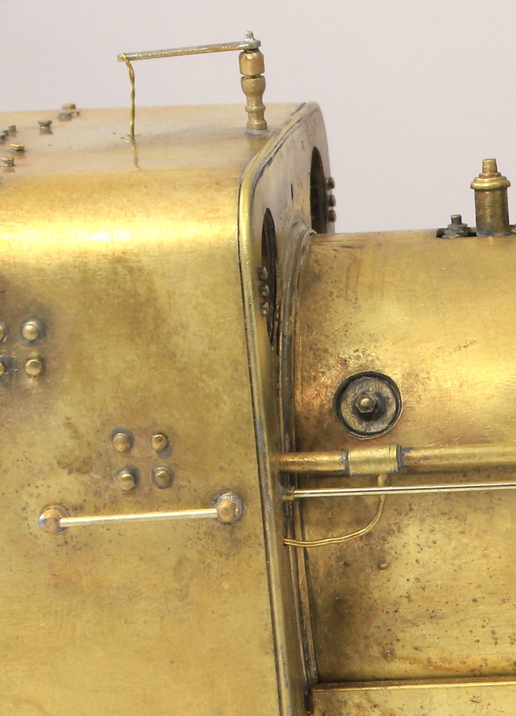
You can see the half etch lines in the shot above. What isn’t apparent is that the half etched lines in the splasher tops are approx. 3mm different from those on the floor etch. I cut at the splasher lines first but needed to cut at the floor lines to get it to fit so anyone else building one of these as a 536 series you need to ignore the lines on the splasher tops and use those on the floor etch.
Once I had it a good fit in the cab, I added the splasher top sandbox filler plates and the fillers themselves. Curiously the splasher tops and the half etched sandbox top plates have a recess/hole for the top which I can only assume is for location purposes as the filler cap needs to be slightly proud of the splasher top. Like those on the front I cut a slice of tube and gently squashed it into an oval with pliers before soldering the top on.
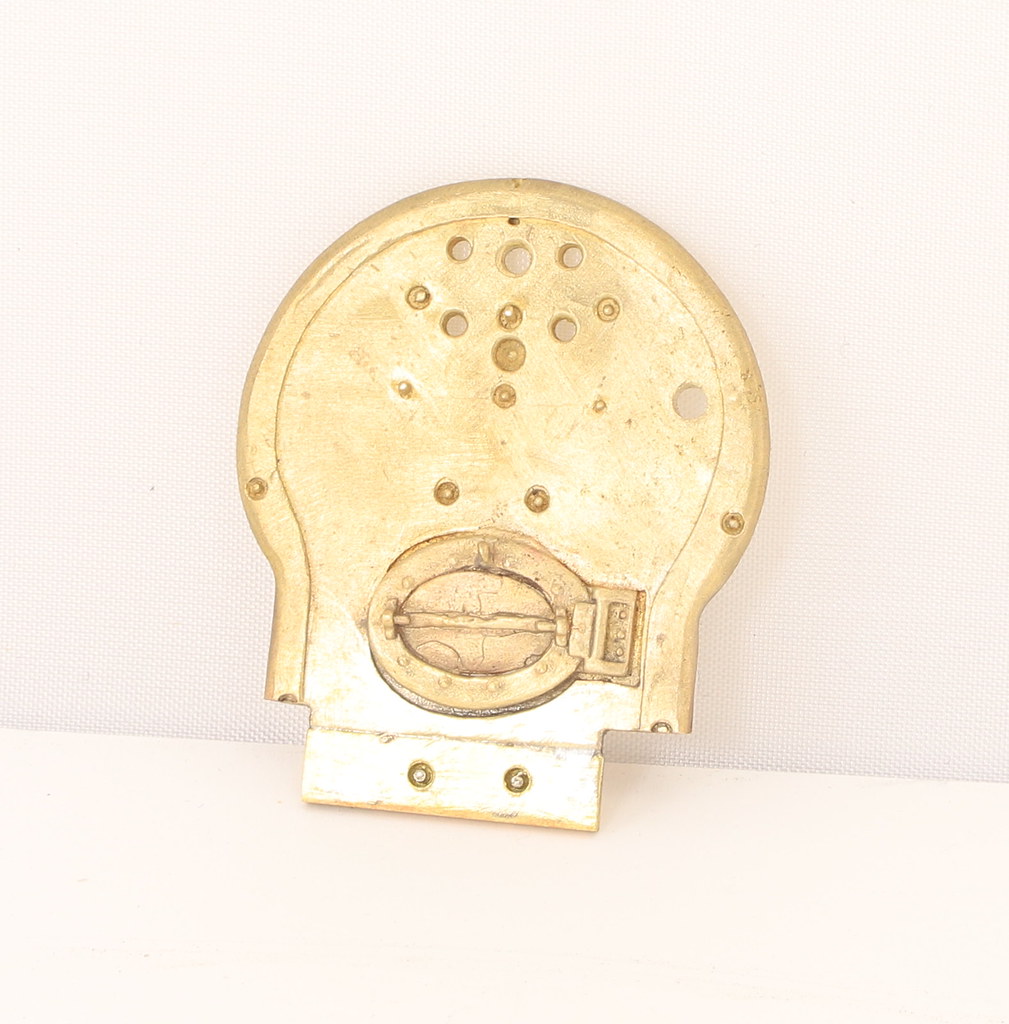
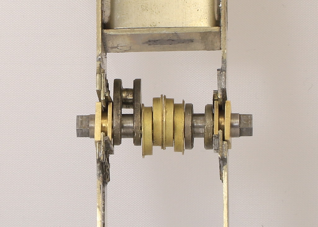
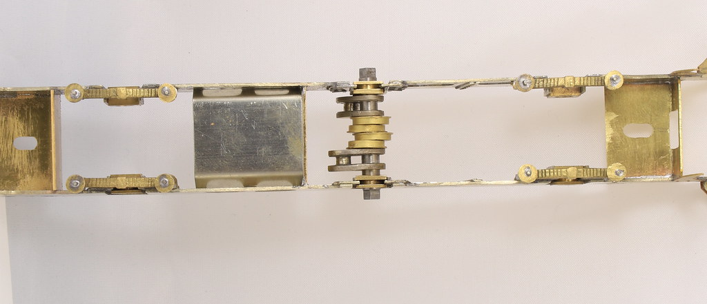
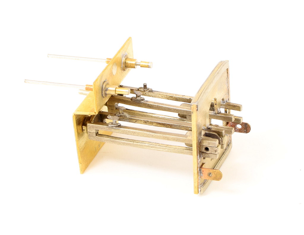
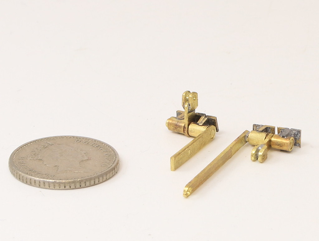
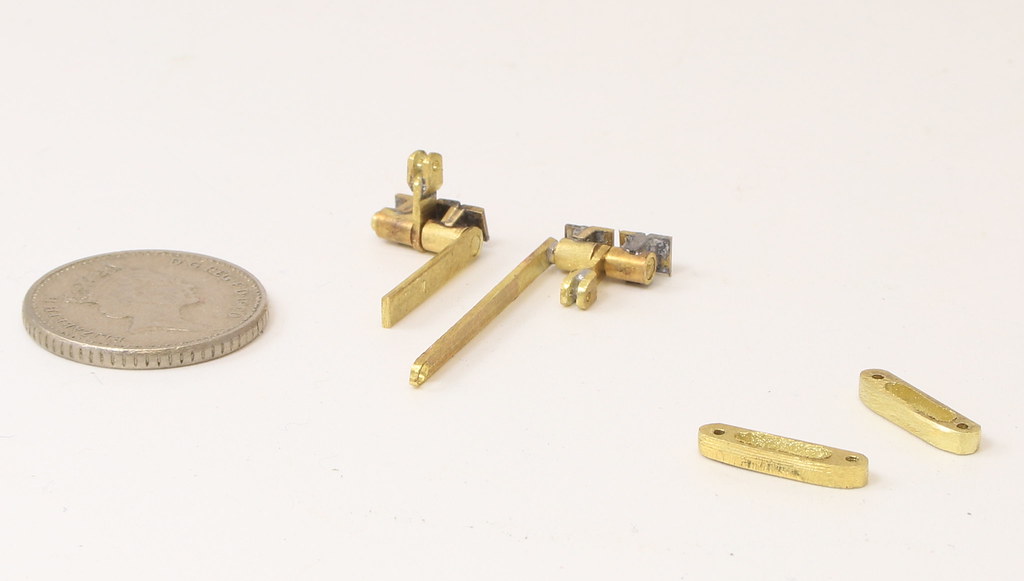
I made up the reverser and fitted it to the cab.
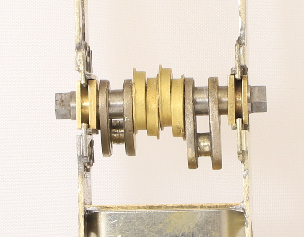
After having a look at the reverser in the C1 I added a couple of bits of scrap etch to give a little more detail – not very clear in the shot below. Strictly speaking the lever should be on the outside of the ratchet plate not in between as shown in the instructions
I decided to leave it as is, as it will be lot in the gloom of the cab.
It was probably a sign that I should have left it alone at this point but for the life of me I could only find two of the four splasher tops. I decided to cut some replacements out of 10 thou sheet on my “Mini Formit” guillotine (which I have used extensively throughout this build). Parts duly cut, the first front sandbox/splasher went on easily then it took over two hours to fit the rest and, in the end, I cut it off the cradle to make it easier to solder from the back.
For whatever reason they sorely tested my patience. It was even more frustrating when trying to fit the ashpan sides as again one went on easily without issue to the second was a nightmare which resulted in the splasher top coming adrift several times before I had both in place to my satisfaction. On the back of that I had an evening off last night.
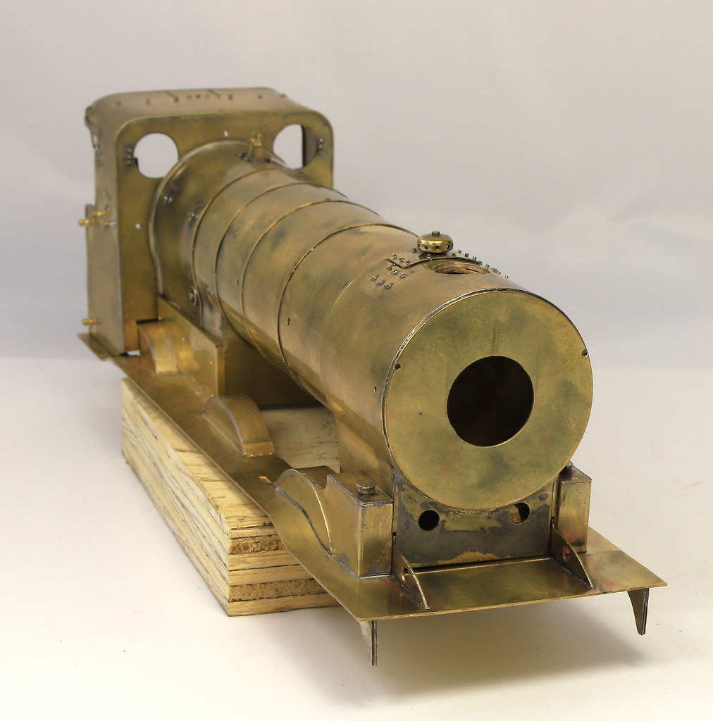
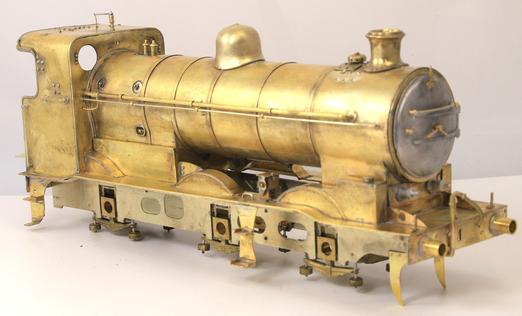
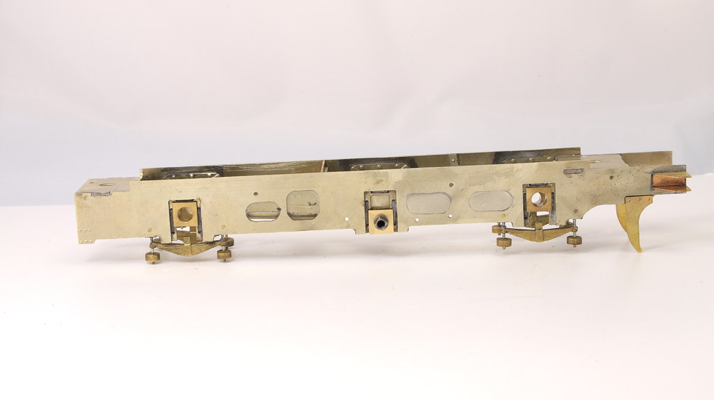
But here is the state of play.
Still a bit of detailing to go on before I fix things together but I am getting there.