Rivermead Central

40057

Western Thunderer
Hi Martin
It‘s such a history lesson reading your thread thank you.
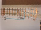
With the flexing of the switch blades braking the solder joints and to keep the points looking as they should with no noticeable alterations would it be worth pivoting the two fixed blades by removing the solder at positions marked with a Blue X and making the two fixed switch blades pivot at the position shown in red on the photo below by using a 12 ba screw or a piece of rod or similar through from the underside of the sleeper into the rail and (if needed closing the gap a little by bending the rail shown in Black so when the diverge position is set the check gap is correct).
David.
View attachment 213705

Hi David

Thank you for your comments and suggestion.

Your idea would certainly work as it removes the need for the switchblades to flex, so there would be no strain on the soldered joints in normal operation. I had considered a similar approach based on cutting through the rails that form the switchblades near the crossing and making them into a separate pivoted assembly, as was done in the post-war scale permanent way. I might try out either, or both, these approaches in future. I am not sure they will be much easier or quicker to do than what I have done so far. Generally, the soldered joints securing the wing rails don’t break, certainly not the joints furthest from the crossing. So I have been reluctant to disturb these as they preserve the relative positions of the different running rails.

My approach to date has not been to alter the way the points operate, but to strengthen the soldered joints so (I hope) they are strong enough not to fail. Additionally, to introduce more flexibility into the connection between the tie bar and the point lever, so the switch blades are free to swing in an arc, rather than just move transversely across. The combination of reduced stresses from a more ‘natural’ flex and stronger joints should be durable, I feel. Come back to WT in 100 years time to find out!

I don’t think the original Lowko Track design is far off being OK for 3’ 2 1/4” radius points. Lowko track was also made in 2’ radius. The distance between the toe of the switch blades and the crossing is obviously far less in 2’ radius points and they are always broken. I have never seen a 2’ turnout with the soldered joints intact. (I was never going to be using such a small radius anyway, so not my problem). In 3’ 2 1/4” radius points with tinplate rails, joints at one or other end of the switchblades have usually failed. Not every time, either because the turnout has had little use or the soldered joint was particularly strong or the tinplate rail was particularly flexible. There is certainly some variation in the rails as to how ‘splayed’ the bottom webs are and this does seem to affect how easily the rails bend. Also the removal of one web from the rail to form the switchblade extends further from the toe in some points than others reflecting the hand-made construction. I have only three factory made Lowko Track points with brass rails. So, based on this very small sample, I would say soldered joints are less likely to fail with brass rails, no doubt because they bend more easily. I have never seen a factory made 4’ radius Lowko Track LH or RH turnout in 0 gauge (these were only listed pre-WW1). However, the ‘complete crossovers’ listed until production of Lowko Track ceased used two 4’ radius points. I have several of these but mostly very distressed and not repairable. It is difficult to distinguish between failed soldered joints due to flexing of the switchblades in use and the damage caused when granny stood on the crossover. My impression though is the extra length of the points in the crossovers reduces the strain on the soldered joints sufficiently for them mostly not to fail.

Based on the above, my conclusion is that a modest strengthening of the soldered joints plus some additional flexibility should be enough to allow 3’ 2 1/4” radius Lowko Track points to be used regularly and not break.
 

Allen M

Western Thunderer
Back in about 1958 I built some 00 points with flexing blades. They gave trouble.
Since then I have always pivoted the blades on 00 0fs and 16mm (0cs). Some times by putting a pivot under each blade but then that also needs a pivot in the tie bar. Then I started to use a pivoted sub assembly, not prototype but very reliable and once weathering & ballast added invisible unless you know and look closely.
14 Complete.JPG

Might be of help
Allen
 

40057

Western Thunderer
Back in about 1958 I built some 00 points with flexing blades. They gave trouble.
Since then I have always pivoted the blades on 00 0fs and 16mm (0cs). Some times by putting a pivot under each blade but then that also needs a pivot in the tie bar. Then I started to use a pivoted sub assembly, not prototype but very reliable and once weathering & ballast added invisible unless you know and look closely.
View attachment 213740

Might be of help
Allen

Thank you, Allen.

There is no doubt that the Lowko Track points (and indeed permanent way points until post-WW2) were not a good design. I certainly wouldn’t build points that depended on the switchblades bending. But I’m not building them, so I hope I have found a way of repairing them and making the least possible change consistent with satisfactory long term operation. Time will tell.
 

40057

Western Thunderer
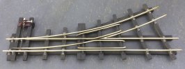
A cleaned-up, 3’-radius, post-war permanent way point:

18751C82-DE58-4AB7-A909-DD29C9E07A76.jpeg

A few hours work was all it needed, and it’s ready to use. There are no signs of wear on the rails, so either this has never been used or it has had very little use. There was some corrosion on the rails — I think phosphoric acid had been used as the flux for the soldered joints during manufacture and not cleaned off properly. Lots of dust on the sleepers. But no damage and no repairs needed, just cleaning. I don’t suppose all my permanent way track pieces will be as easy to renovate as this — but this was far, far simpler and quicker than putting a Lowko Track point into good, useable condition.

I would comment that post-war permanent way points always seem to be very accurately made. The switch blades fit tightly against the stock rails, the check rail spacing is correct and consistent. Standard Bassett-Lowke wheels run through the crossings perfectly smoothly with no drop or jar. In terms of their design, functionality and appearance, these post-WW2 permanent way points are clearly superior to Lowko Track points. However, I will stick with Lowko Track for most of the layout because it is contemporaneous with much of my rolling stock, so a more appropriate track. I will get Cavendish Goods laid with permanent way, see how it looks, and then consider if I might do another part of the layout in permanent way track as well.

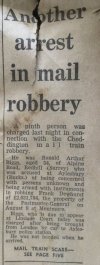
By way of a PS, when I opened the box containing the above 3’ radius point, I found a sheet of newspaper had been used as a wrapping. This turned out to be the front and back pages of the Sheffield Telegraph of 5 September 1963. Quite possibly the date the points were last packed up and put away. Anyway, it was this front page story on view when I lifted off the box lid that caught my eye:

E9A64D0D-A73E-445A-86AD-EF54CBDCA17F.jpeg

7E3A3A02-0819-4A16-A558-D4A3656474CA.jpeg
 

oldravendale

Western Thunderer
I lived a matter of a few hundred yards from the bridge where that happened for quite a few years. When passing it was difficult to comprehend the drama that ensued...

Brian
 

jonte

Western Thunderer
I don't wish to boast but I had a 'bit' part as a 'police extra' in the film "Robbery" based on that incident. It starred the late Sir Stanley Baker - a fine gentleman with whom I was privileged to chat when on the set.
Apologies for hi-jacking this fascinating thread ;)!

Roger

No doubt you were the dashing fellow who made Mr. Baker look, well, ordinary :thumbs:

A signed autograph, if I may be so bold Roger.

Oh, and sign it to ‘the kid who used to wave to passing Police cars’ ;)

Jon
 

40057

Western Thunderer
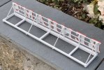
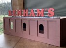
The roof advertising sign for the Benham’s factory building is nearly finished:

172ADB97-4E53-4327-AC31-096981BF4925.jpeg

I have added diagonal supports for the frame on which the letters are mounted. I still need to put some matt white paint over the joints at each end of the diagonals, and I will probably spray on a thin coat of matt varnish. But otherwise, all done.

I have put in just four diagonal supports which I am sure is too few for a full size equivalent sign. But only the ones at each end are really going to be visible when the building is in place on the layout — as I think is apparent from the above photograph. From any normal viewing angle, all anyone is going to notice is that there is a supporting framework behind the letters.

2C1990E5-380F-4684-872E-6BEA56B97497.jpeg
 

40057

Western Thunderer
The roof advertising sign for the Benham’s factory building is finished.

It was officially declared completed less than an hour ago.

Here it is in place on the still unfinished factory:

958EEB8E-85D6-4768-BFE5-11AE52EEDBFC.jpeg

I have made no progress with the building itself for months, due largely to concentrating effort on the warehouse building. However, the roof sign was easily the most complicated of the remaining tasks needed to get the factory building finished, so that’s a significant step forward.
 

40057

Western Thunderer
Having decided to use post-WW2 Scale Permanent Way for part of my layout, for context I had better provide some general information about the track system. The Scale Permanent Way I am going to use was manufactured between the late 1940s and the mid ‘60s. I shall only be using ‘standard’ brass track at Cavendish Goods, i.e. with no third rail for electric traction. In addition to the standard Scale Permanent Way track, variants with steel rails and fewer sleepers were offered, generally at lower cost; also electric track fitted with a raised centre third rail, and; right at the end of production, points insulated for use on two-rail electric railways (the plain line track was insulated anyway, by the wooden sleepers).

The post-WW2 Scale Permanent Way was essentially similar to the Scale Permanent Way track Bassett-Lowke had offered since 1905. Many details changed over time. The rail section became smaller and closer to scale. In the 1920s and before, Scale Permanent Way was made in 15” lengths and with a standard curve of 3’ 2 1/4” radius — i.e. the same as Lowko Track. Early Scale Permanent Way track always had separate hardwood keys. But the basic approach did not change — creosoted wood sleepers, solid drawn rail, cast lead alloy chairs fastened down with tiny spikes. Track of similar construction was offered by several other manufacturers. It was the ‘industry standard’ for fifty years.

By the time Bassett-Lowke’s retail shops closed in the 1960s, they were also selling Peco ‘0’ gauge track as an alternative to Scale Permanent Way. What had been the norm since the early 20th century, with only relatively minor variation, was quickly superseded by something quite different. Arguably, the replacement of Scale Permanent Way by Peco Streamline represents the only paradigm shift in the history of 0 gauge model railway track.

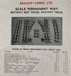
The post-WW2 Scale Permanent Way was sold in 18” lengths, though shorter ‘distance pieces’ were available as well. The standard radius of curve was described as 3’. Curves of 3’ 3” radius were also offered to enable the laying of double track. There was a comprehensive range of pointwork. The track pieces offered in the mid-1950s are shown here:

6C873343-7C31-4907-9C9D-CAC52ED3AD8F.jpeg

(The point levers shown in the above illustration are of a type offered since before WW1 and I have never seen them fitted to post-WW2 track).

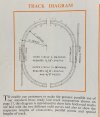
Despite the curves always being described as 3’ or 3’ 3” radius in lists and on the boxes, slightly different dimensions were given in a helpful diagram published in the early 1950s catalogues:

351A6BD6-D689-4023-B1E1-3C037B92906D.jpeg

I will have to check the actual dimensions carefully before starting to fasten down the track for Cavendish Goods. I am confident I can fit in a suitable run round and sidings, but there is very little space to spare. Compared with Lowko Track, the track panels are 3” longer and the radius of curve slightly larger or slightly smaller. My intention is that the run-round loop is based on a 90 degree arc of double-track. Fortunately, I have several of the 3’ 3” radius 6”-long distance pieces, one of which will be essential for constructing the loop. I think I also have all the points I need but, if not, post-war Scale Permanent Way is easy to obtain in good condition.
 

40057

Western Thunderer
This terrible cold, wet, windy weather is a disaster for getting on with the garden — but great for making time for modelling.

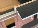
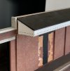
I have just fitted the vertical coping to the ends of the raised wall section in the centre of the Benham’s warehouse building:

D83DF0BC-723D-45C2-955B-DABC9E2C8B5E.jpeg

1DEE1BC8-0C96-4BD7-B0D9-E554737CCA7A.jpeg

The two holes are for a couple of moulding pins. These will help strengthen the joint between the top c. 1 cm of the wall, which is integral with the canopy structure, and the rest of the building.

I was concerned whether I could make such a large separate subassembly as the whole canopy and top section of the wall accurately enough for it to fit exactly onto the rest of the building. In particular, my worry was twist due to warping of the wood in either component. But all is well. Everything lines up as it should.
 
Top