decauville1126
Western Thunderer
Well I finally took the plunge and it's turned out to be one heck of a conversion! Definitely model engineering rather than railway modelling.
First thoughts were to rewheel with Gibson Q1's, but the Leader has 2.5mm axles and Gibsons have, or should have, a domed front. So I elected to retyre. Might have been possible to reprofile and then reduce the face of the existing wheels but new axles would still be required and the draft on the wheel bushes on the insulated side - the other is metal-to-metal - is quite steep so the issue of wheels popping off the axles would still be a worry.
First is the bodyshell is easy to remove. just spring out the sides around the innermost axles and slide some still card up around the middle ones and off it slides.

Now removing the bogies needs the circuit board to be undone - 3 tiny screws - and laid off to one side. Note connections then unsolder the pickup wires from the underside of the board.

Now necessary to remove the clip on the bogie tower. Two pieces of 2mm silver steel 55mm long were filed as shown, pop one each side into the handles, squeeze together and wiggle off. Lift out the wormwheel and shaft.


The bogie outer frame unclips downwards. I worked from the back, along the sides, then the front. This leaves the bare bogie with gear train, wheels, and pickups. The wheelsets pop out by pressing downwards. The wheel design is what it is so a real compromise from here in.
The profile difference shown below with the Saclefour Society form tool for comparison.

Wheels all removed from axles using a puller. Bearings and gear also removed and put aside. New axles from 2.5mm EN1A steel cut to 22.50mm long and ends centred.
I decided 18.40mm would be a good compromise to turn the wheels down to and also give 0.8mm tread thickness on the tyres. Tyres were next made from 25mm diameter leaded EN1A steel by drilling 5/8" then parting off to 2.5mm thick on one of the bigger lathes I have access to. Did 14 just in case. All the rest of the machining was done on a Unimat 3 without difficulty.
Using a WW step chuck the tyres were faced down to 2.0mm thick.

Then were bored out bigger.

A mounting jig was made and the tyres machined down to 20.8mm over flange using the form tool. No fine feeding, just get into it and keep going. Slowest possible speed.

No need to worry about concentricities as that gets done right at the end, with the flange and tread used as data. So a pleasing stack of part-completed tryes.

These were then bored out to 18.40mm diameter ready for fitting. At 0.8mm I think it's probably the minimum tyre thickness I'd be happy with. Got to do a Rapido Ivor when it arrives at possibly the same thickness, or maybe thinner. Hope not.
Time to modify the wheels, with no going back after this stage. I decided to leave them at 2.8mm thickness as it didn't show too much from the front of the loco. mounted in step chuck, drilled out 3.2mm I think, then mounted on a mandrel made to suit and the tread completely machined off down to 18.40mm and a tad so the tyre easily slid over.

Now to tyre fitting. Another mandrel made to allow the tyre to protrude about 0.2mm to give a visible rim and to be held whilst fixing with Loctite 601. Removed from the mandrel as soon as the tyre was gripped then left for 48 hours. Tyre was later deinsulated using a thin bead of silver conductive paste which gave quite a low resistance.


Back into a step chuck and bored out to 4.0mm - just enough to leave the rim of the wheel boss showing.

A batch of top hat delrin bushes without bores were machined and pressed in, about 0.002" interference seemed right. 5.0mm bigger diameter to clear pickups as I used the existing ones extended.
With the wheel gripped in the step chuck again (they come in a set of sizes) drilled 2.45mm diameter to be a good press fit on the axles.
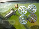
I did do a trial assembly of one axle to prove the process, but by the time the sixth is done it's a production line and surprisingly quick. Now came a diversion into fitting the 3D printed wheel inserts provided by Vectis 3D Models. Painstaking work but worth it I felt. They are very small and easily lost, and require patience. Half a wheel at a time became the norm. They need cutting from the supports which I carefully with a jewellers piercing saw the threaded onto a piece of wire for safe keeping. A filing jig from scrap brass held each one whilst it's back was filed down to 1.5mm deep and the tube allowed the wire to be threaded up for flicking them out onto.

As I can only attach 16 images it seems I'll have to continue this in a following post. Never posted a workshop thing before so a learning curve.
First thoughts were to rewheel with Gibson Q1's, but the Leader has 2.5mm axles and Gibsons have, or should have, a domed front. So I elected to retyre. Might have been possible to reprofile and then reduce the face of the existing wheels but new axles would still be required and the draft on the wheel bushes on the insulated side - the other is metal-to-metal - is quite steep so the issue of wheels popping off the axles would still be a worry.
First is the bodyshell is easy to remove. just spring out the sides around the innermost axles and slide some still card up around the middle ones and off it slides.
Now removing the bogies needs the circuit board to be undone - 3 tiny screws - and laid off to one side. Note connections then unsolder the pickup wires from the underside of the board.
Now necessary to remove the clip on the bogie tower. Two pieces of 2mm silver steel 55mm long were filed as shown, pop one each side into the handles, squeeze together and wiggle off. Lift out the wormwheel and shaft.
The bogie outer frame unclips downwards. I worked from the back, along the sides, then the front. This leaves the bare bogie with gear train, wheels, and pickups. The wheelsets pop out by pressing downwards. The wheel design is what it is so a real compromise from here in.
The profile difference shown below with the Saclefour Society form tool for comparison.
Wheels all removed from axles using a puller. Bearings and gear also removed and put aside. New axles from 2.5mm EN1A steel cut to 22.50mm long and ends centred.
I decided 18.40mm would be a good compromise to turn the wheels down to and also give 0.8mm tread thickness on the tyres. Tyres were next made from 25mm diameter leaded EN1A steel by drilling 5/8" then parting off to 2.5mm thick on one of the bigger lathes I have access to. Did 14 just in case. All the rest of the machining was done on a Unimat 3 without difficulty.
Using a WW step chuck the tyres were faced down to 2.0mm thick.
Then were bored out bigger.
A mounting jig was made and the tyres machined down to 20.8mm over flange using the form tool. No fine feeding, just get into it and keep going. Slowest possible speed.
No need to worry about concentricities as that gets done right at the end, with the flange and tread used as data. So a pleasing stack of part-completed tryes.
These were then bored out to 18.40mm diameter ready for fitting. At 0.8mm I think it's probably the minimum tyre thickness I'd be happy with. Got to do a Rapido Ivor when it arrives at possibly the same thickness, or maybe thinner. Hope not.
Time to modify the wheels, with no going back after this stage. I decided to leave them at 2.8mm thickness as it didn't show too much from the front of the loco. mounted in step chuck, drilled out 3.2mm I think, then mounted on a mandrel made to suit and the tread completely machined off down to 18.40mm and a tad so the tyre easily slid over.
Now to tyre fitting. Another mandrel made to allow the tyre to protrude about 0.2mm to give a visible rim and to be held whilst fixing with Loctite 601. Removed from the mandrel as soon as the tyre was gripped then left for 48 hours. Tyre was later deinsulated using a thin bead of silver conductive paste which gave quite a low resistance.
Back into a step chuck and bored out to 4.0mm - just enough to leave the rim of the wheel boss showing.
A batch of top hat delrin bushes without bores were machined and pressed in, about 0.002" interference seemed right. 5.0mm bigger diameter to clear pickups as I used the existing ones extended.
With the wheel gripped in the step chuck again (they come in a set of sizes) drilled 2.45mm diameter to be a good press fit on the axles.
I did do a trial assembly of one axle to prove the process, but by the time the sixth is done it's a production line and surprisingly quick. Now came a diversion into fitting the 3D printed wheel inserts provided by Vectis 3D Models. Painstaking work but worth it I felt. They are very small and easily lost, and require patience. Half a wheel at a time became the norm. They need cutting from the supports which I carefully with a jewellers piercing saw the threaded onto a piece of wire for safe keeping. A filing jig from scrap brass held each one whilst it's back was filed down to 1.5mm deep and the tube allowed the wire to be threaded up for flicking them out onto.
As I can only attach 16 images it seems I'll have to continue this in a following post. Never posted a workshop thing before so a learning curve.