
You are using an out of date browser. It may not display this or other websites correctly.
You should upgrade or use an alternative browser.
You should upgrade or use an alternative browser.



mickoo
Western Thunderer
Pushing the new 3D printer today. Sometimes the stars align, not perfectly, but enough to show you the way forward.
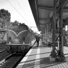
For those who have no idea what it is I'll explain and save y'all looking back in the thread, it's a Br110 cab module, Germanys most prolific class of electric locomotive, they come in two flavours, standard cab and this, the Bugelfaltre which roughly translates to crease stemming from the ridge running down the middle of the cab.
I've wanted a Bugelfaltre for as long as I can remember and kits are non existent, I don't think there's even a RTR version, not unless you want to part with several thousand £££.
Drawing it up in CAD was a challenge but the hobby printer failed miserably and I'd all but given up of ever making one.
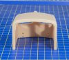
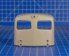
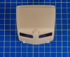
But, the new printer does a much better job, it's not perfect by along short, some mild warpage and I've not built in any sacrificial edges to help that and aid post clean up. One of the windscreen recesses has blown through and the left side window openings are a little rough on the top edge, not big issues as there's a thin etch with rubber beading designed to fit in the windscreen and quarter lights.
Initially I was going to just mount this on an etch frame but looking at the 1:1 photo (Hamburg in my youth spotting days) it'll be better if I add the lower section as well plus the door step recess, I'll also add the gutter strip and more details.
The door window now needs an internal recess to take the window and a design revision to stop the top edge being so rough.
So, for a rough throw it in the printer and see what happens I'm more than pleased, actually that's a bit of a gross understatement
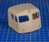
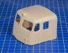
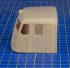
For those who have no idea what it is I'll explain and save y'all looking back in the thread, it's a Br110 cab module, Germanys most prolific class of electric locomotive, they come in two flavours, standard cab and this, the Bugelfaltre which roughly translates to crease stemming from the ridge running down the middle of the cab.
I've wanted a Bugelfaltre for as long as I can remember and kits are non existent, I don't think there's even a RTR version, not unless you want to part with several thousand £££.
Drawing it up in CAD was a challenge but the hobby printer failed miserably and I'd all but given up of ever making one.
But, the new printer does a much better job, it's not perfect by along short, some mild warpage and I've not built in any sacrificial edges to help that and aid post clean up. One of the windscreen recesses has blown through and the left side window openings are a little rough on the top edge, not big issues as there's a thin etch with rubber beading designed to fit in the windscreen and quarter lights.
Initially I was going to just mount this on an etch frame but looking at the 1:1 photo (Hamburg in my youth spotting days) it'll be better if I add the lower section as well plus the door step recess, I'll also add the gutter strip and more details.
The door window now needs an internal recess to take the window and a design revision to stop the top edge being so rough.
So, for a rough throw it in the printer and see what happens I'm more than pleased, actually that's a bit of a gross understatement

adrian
Flying Squad
So you should be - that's pretty damn good to my untutored eye. Normally you can tell when something has been 3D printed, the striations and layer lines around compound curves usually gives the game away. Maybe the faintest trace of lines inside the top headlight housing but otherwise that looks like a full resin casting from a master to me.So, for a rough throw it in the printer and see what happens I'm more than pleased, actually that's a bit of a gross understatement

SimonT
Western Thunderer
I would say that is the dog's bollucks for a first shot with that shape. (Archie say's "If they are his, can he have tham back" ).
).
I had some success by making the window recesses deeper and then filing back. This allows plenty of supports in the area without worrying about their effect on the outside finish. I had an idea to put a 'half etch' marker line on the surface to indicate how far to file back to but never got to try it.
Simon
).I had some success by making the window recesses deeper and then filing back. This allows plenty of supports in the area without worrying about their effect on the outside finish. I had an idea to put a 'half etch' marker line on the surface to indicate how far to file back to but never got to try it.
Simon
mickoo
Western Thunderer
More Bugelfaltre, some good, some bad.
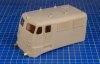
The quarter light and cab door window frames blew through in places (orientation) and the joint between cab and #2 end wasn't the best. However a trick from the miniature modellers makes a lovely smooth joint even though the darker gap can be seen underneath on one side.
The vents came out nicely except their fixing rivets didn't export over from CAD on this run , all the pre test ones did. The roof covers are ok but an error in the body recess finds them a little loose. The recess will allow all three types of vent to be fitted if required, these being the smallest and hence determine the size of the required recess.
Not sure on the pantograph supports, they look ok but the resin is a witch to get flat and smooth to match the roof profile, I could employ the trick above and blend them in....tricky....or some other method not yet devised.....the answer will be in the bottom of a beer glass, the question is how many do I have to empty to find it
Buffer beam and front end fittings are pretty much perfect, the brass tubes will be soldered to a brass sheet bonded to the inside as will the coupling hook at some point.
I am tempted to make these two units as one and print as such, it will fit, but at 19 hour print it only needs one small defect to destroy a lot of time and resin. Once again another beer glass bottom solution will present it's self, probably not in the same one as above....sigh
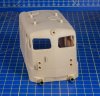
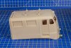
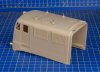
The quarter light and cab door window frames blew through in places (orientation) and the joint between cab and #2 end wasn't the best. However a trick from the miniature modellers makes a lovely smooth joint even though the darker gap can be seen underneath on one side.
The vents came out nicely except their fixing rivets didn't export over from CAD on this run
, all the pre test ones did. The roof covers are ok but an error in the body recess finds them a little loose. The recess will allow all three types of vent to be fitted if required, these being the smallest and hence determine the size of the required recess.Not sure on the pantograph supports, they look ok but the resin is a witch to get flat and smooth to match the roof profile, I could employ the trick above and blend them in....tricky....or some other method not yet devised.....the answer will be in the bottom of a beer glass, the question is how many do I have to empty to find it
Buffer beam and front end fittings are pretty much perfect, the brass tubes will be soldered to a brass sheet bonded to the inside as will the coupling hook at some point.
I am tempted to make these two units as one and print as such, it will fit, but at 19 hour print it only needs one small defect to destroy a lot of time and resin. Once again another beer glass bottom solution will present it's self, probably not in the same one as above....sigh
mickoo
Western Thunderer
Rapidly came to the same conclusion, hence MkIII will have such features as well as sacrificial edges in other important places.I would say that is the dog's bollucks for a first shot with that shape. (Archie say's "If they are his, can he have tham back"
I had some success by making the window recesses deeper and then filing back. This allows plenty of supports in the area without worrying about their effect on the outside finish. I had an idea to put a 'half etch' marker line on the surface to indicate how far to file back to but never got to try it.
Simon
mickoo
Western Thunderer
Cheers, I'll let you know in 12 hrs how the combined cab/traction motor vent module came out.For something that is pigging ugly it looks rather good. The join has worked very nicely. If you can get joints like that I would forget the 19hour build and make it the Johnny Cash way, but do try to do it all in one year!
Currently it's split into five pieces. A cab either end....obviously, two traction motor vent rooms and the centre transformer and power section. A recess in the roof will hold the raised roof section (with four pegs to lock the vent rooms in place) over the power module, note, it's longer at one end, which is a pain as it means each vent room has a different roof section recess.
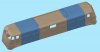
Each section interlocks with it's neighbour, at the lower floor level with tapered peg and recess joints, mid side and roof with tabs (not yet modelled on the middle section).
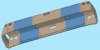
The bulged areas will have knurled nutserts fitted, 10 or 8BA or what ever fits in the hole really (no forward planning here then
 ), these'll hold a full length brass or NS floor in place, for added strength the floor will fold down at the edges and end flush with the bottom of the resin body sides.
The first joint behind the cab is close to the door recess and the outer pantograph supports....not ideal. I also tried a print that was split between vents 1/2 (not 3/4 and 5/6 as above) but again the pantograph supports at the inner end are near the joint. The problem with a split at vent 2/3 is how to split the mid section up effectively.
A middle section running from 2/3 to 5/6 is massive and can only be printed vertically, it'd work, vertical orientation works really well but ramps the time up. The cab fronts can't realistically be done vertically as the nose ends up being printed last, which due to the way this type of process works, leaves the door wide open to distortion or faults in an area that is hard to recover.
Ideally the less joints the better, however, one single fault or error is a massive waste of material.
Currently the power module has a opening (window) in the middle, that only came later with (I believe) service up grades in later lives, but the opening is the same size as the vents so a vent can be fitted for those engines with full length grills.

paratom
Western Thunderer
The 3D prints look fantastic, what printer are you using?Pushing the new 3D printer today. Sometimes the stars align, not perfectly, but enough to show you the way forward.
For those who have no idea what it is I'll explain and save y'all looking back in the thread, it's a Br110 cab module, Germanys most prolific class of electric locomotive, they come in two flavours, standard cab and this, the Bugelfaltre which roughly translates to crease stemming from the ridge running down the middle of the cab.
I've wanted a Bugelfaltre for as long as I can remember and kits are non existent, I don't think there's even a RTR version, not unless you want to part with several thousand £££.
Drawing it up in CAD was a challenge but the hobby printer failed miserably and I'd all but given up of ever making one.
But, the new printer does a much better job, it's not perfect by along short, some mild warpage and I've not built in any sacrificial edges to help that and aid post clean up. One of the windscreen recesses has blown through and the left side window openings are a little rough on the top edge, not big issues as there's a thin etch with rubber beading designed to fit in the windscreen and quarter lights.
Initially I was going to just mount this on an etch frame but looking at the 1:1 photo (Hamburg in my youth spotting days) it'll be better if I add the lower section as well plus the door step recess, I'll also add the gutter strip and more details.
The door window now needs an internal recess to take the window and a design revision to stop the top edge being so rough.
So, for a rough throw it in the printer and see what happens I'm more than pleased, actually that's a bit of a gross understatement
View attachment 140293
View attachment 140294
View attachment 140295
View attachment 140296
View attachment 140297
View attachment 140298

michael080
Western Thunderer
Very exciting. A well know "Neubau E-Lok" that can still be seen today. Unfortunately this class was seen so frequently that I don't have any picture.
I hope you are not planning to use BA screws in a German engine, would you?
Michael
I hope you are not planning to use BA screws in a German engine, would you?
Michael
mickoo
Western Thunderer
Cheers, it's a Form3.The 3D prints look fantastic, what printer are you using?
mickoo
Western Thunderer
Shsss, no one will ever knowVery exciting. A well know "Neubau E-Lok" that can still be seen today. Unfortunately this class was seen so frequently that I don't have any picture.
I hope you are not planning to use BA screws in a German engine, would you?
Michael
My biggest problem is that it's not fast enough
, I'm drawing CAD objects faster than it can print A few long term 'want's have moved up the interest table, a DSB Mz, any Mk will do, the SNCB HLD 55/62 and the NS 16/17/18xx cab would be a perfect for 3D printing....which then opens doors to a raft of SNCF locos.
Last edited:
mickoo
Western Thunderer
I use Autocad but it's becoming too restrictive, I may go back to Studio Max which was killer for complex and compound shapes, or, move onto something else more suited to 3D work.
The problem with studio max is that it deals in real units which flight and train sims use as they model real world environments scale wise, what it didn't do so well was scaled units, it couldn't cope with vertices so close together.
Citation X was probably the most exciting project I did, I'm no fan of biz jet but this little baby was superb and the contract manager a dream to work for, every one knew their place and work boundary, probably the best project I ever did.
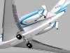
Still born Phantom project just before I threw the towel in.
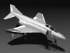
Still born rail sim models before the group went bust with the owner ripping everyone off, sour grapes, not all, don't like being taken for a ride and ripped off out of pocket.
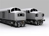
Rail sim was much lower fidelity than flight sim, simply down to the sheer number of models you get in one scene at a station or yard, trains sim didn't use LOD, still doesn't as far as I know. Flight sim did and the difference on frame rates and detail was marked.
The problem with studio max is that it deals in real units which flight and train sims use as they model real world environments scale wise, what it didn't do so well was scaled units, it couldn't cope with vertices so close together.
Citation X was probably the most exciting project I did, I'm no fan of biz jet but this little baby was superb and the contract manager a dream to work for, every one knew their place and work boundary, probably the best project I ever did.
Still born Phantom project just before I threw the towel in.
Still born rail sim models before the group went bust with the owner ripping everyone off, sour grapes, not all, don't like being taken for a ride and ripped off out of pocket.
Rail sim was much lower fidelity than flight sim, simply down to the sheer number of models you get in one scene at a station or yard, trains sim didn't use LOD, still doesn't as far as I know. Flight sim did and the difference on frame rates and detail was marked.
michael080
Western Thunderer
Sadly, there is no way to import CAD Files from one system to another one. All you can get is a dumb blob that lost all parametric features.
Btw., I am using solidworks at home with a license from my EAA-society membership. I have to admit that i don't have any interest in experimental aircraft, but 40 USD a year for a SW-license is unbeatable.
Michael
Btw., I am using solidworks at home with a license from my EAA-society membership. I have to admit that i don't have any interest in experimental aircraft, but 40 USD a year for a SW-license is unbeatable.
Michael
mickoo
Western Thunderer
Long time since there's been any Euro stuff on here, the recent DSB My should really have been here but that's an opportunity passed.
Many years ago and I mean many, I picked up a HO Roco TEE VT11 set from a hobby shop in Denmark, it was all my spending money and more but I had to have it, over the years it got dabbled with, a half hearted attempt to convert to the units DSB bought came to nowt other than a respray in red and silver, something I regret now and am looking for a good condition replacement for the collection.
Fast forward to last week and a tip off some Euro stuff was in an online auction and I fell into the ROCO lot, sat there were two factory converted units for the DSB, including the intermediate cab car. I'd no idea Roco had even done this and better yet they offered all three liveries at some point, like anything special and short run tracking them down is hard work.
There were two in the auction and I let the first go to see what sort of price it would fetch, I should have picked that one up two in hindsight as the DSB ran them for a lot of the journey as a double set.
First the real deal.
Power car at Aahus way back in my teens waiting to head south.
BTW they sounded lovely with their Teutonic MAN engines and I never heard one ever get thrashed, they had so much power (to weight ratio) they just glided away.
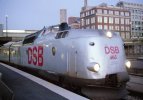
This was their latest and last livery and possibly the most striking.
The intermediate cab car at Skanderborg, this bridge was just up the road from my grand parents house (400yds), my brother and I would always race up here at the end of the day to see the Lyntog (Lightening Train) roll by, a true Rolls Royce they made little sound and seemed to ride on glass.
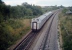
I've no idea why this is a half set as the Evening train was always booked as a double set from Aahus to Fredericia where it split, one half went to Copenhagen via the Store Belt ferries, the other went west to Esbjerg but I'm not sure on that.
The winning bid turned up today, superb box and packing condition so very pleased there as it adds to the value, inside a lovely 4 car half Lyntog set, this one being in the very early colors they were introduced with. The intermediate scheme was all over red with white stripe down the side and a big white DSB on the nose.
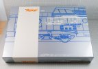
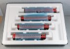
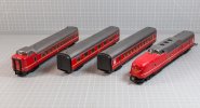
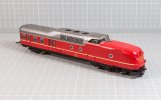
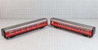
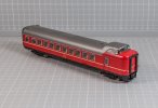
It looks like the power car cab glazing has shifted, probably Mr Pat and his cat so that'll need sorting. I've got no layout plans for DSB so it's really a show case model but it is a nice to have memory jogger from a care free life on holiday.
Many years ago and I mean many, I picked up a HO Roco TEE VT11 set from a hobby shop in Denmark, it was all my spending money and more but I had to have it, over the years it got dabbled with, a half hearted attempt to convert to the units DSB bought came to nowt other than a respray in red and silver, something I regret now and am looking for a good condition replacement for the collection.
Fast forward to last week and a tip off some Euro stuff was in an online auction and I fell into the ROCO lot, sat there were two factory converted units for the DSB, including the intermediate cab car. I'd no idea Roco had even done this and better yet they offered all three liveries at some point, like anything special and short run tracking them down is hard work.
There were two in the auction and I let the first go to see what sort of price it would fetch, I should have picked that one up two in hindsight as the DSB ran them for a lot of the journey as a double set.
First the real deal.
Power car at Aahus way back in my teens waiting to head south.
BTW they sounded lovely with their Teutonic MAN engines and I never heard one ever get thrashed, they had so much power (to weight ratio) they just glided away.
This was their latest and last livery and possibly the most striking.
The intermediate cab car at Skanderborg, this bridge was just up the road from my grand parents house (400yds), my brother and I would always race up here at the end of the day to see the Lyntog (Lightening Train) roll by, a true Rolls Royce they made little sound and seemed to ride on glass.
I've no idea why this is a half set as the Evening train was always booked as a double set from Aahus to Fredericia where it split, one half went to Copenhagen via the Store Belt ferries, the other went west to Esbjerg but I'm not sure on that.
The winning bid turned up today, superb box and packing condition so very pleased there as it adds to the value, inside a lovely 4 car half Lyntog set, this one being in the very early colors they were introduced with. The intermediate scheme was all over red with white stripe down the side and a big white DSB on the nose.
It looks like the power car cab glazing has shifted, probably Mr Pat and his cat so that'll need sorting. I've got no layout plans for DSB so it's really a show case model but it is a nice to have memory jogger from a care free life on holiday.
mickoo
Western Thunderer
I'm not sure if this goes in my European thread as I'm not sure how far Europe actually extends Eastward........But I don't have a global thread so it might as well go here.
Something a little more left field, well a lot more left field, a long standing and niggling itch needed scratching, it's also a good test to see how the Saturn 2 8K copes with large (very large) objects. After much testing I've nearly got the support structure and orientation dialed in, this one was almost perfect but got damaged whilst extracting the support structure.
I'll keep it as a paint and weathering test pig and as a basis to work out how to smooth some areas that need doing post processing.
The large objects with broad rounded faces has thrown up something new, nothing to do with the resin, machine or artwork, it's to do with the export model, Autocad doesn't make perfect round faces, instead it makes them from many small flat faces (lands). Normally this is no issue on smaller parts as the lands are so fine as to be near invisible, the larger the part the bigger the lands, Autocad seems to keep the same number of lands to radius when you scale up, rather than keep them the same size and add more to make the surface smoother.
It's quite a big problem as you need to post process them smooth so you need to make sure those surfaces do not have any surface detail. The worst areas are the cant rail radii and the nose corners, it's even present on the nose front but not the buffer beam as that's three flat faces. On the cant rail are two sand fill ports (sans lids) and these might have to be changed from raised boxes to hollow square holes that the enclosure drops into and the gap sealed up. The same applies to the nose, I might have to make the star and MU socket groups are separate parts fitted later.
Essentially it's a Soviet block dual unit electric engine, with 9000 units to choose from spread over what was the whole of the cold war empire and dozens of classes there are one or two variations, this one being one of the semi permanently coupled triple sets. Once you have the basic cab and shell then the rest is down to detail differences, vent placement windows styles and roof fittings. Even then you can carve the nose off and fit the later more angular ones to model those later classes.
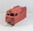
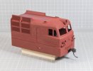
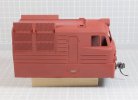

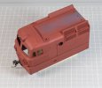
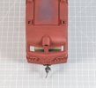
There's still a little kick up at the base toward the rear so I need to fine tune my angles and support structure, problem is, at 50 microns it take over 16 hours to churn out and eats a ton of resin, I can just squeak four cab units from one litre of resin.
The other down side is the resin, FNG has a tendency to separate and marble quite quickly, so 16 hour prints run the risk of the resin changing properties during the process, it'll be worse at 30 microns and I've no idea how it would cope with a 10 micron run which I may need to do to ease the layering on the cab roof front and nose top.
I've only smoothed (very roughly) the LH side of the model so the layering is still evident on the RH side if you look closely. The 3D model is a bit rough on the cab top corners as Autocad doesn't so this sort of thing well, they'll need smoothing better on later runs but I'm not overly concerned as I'd like to use brass strip to replicate the gutter eventually; that's going to be fun to form and fit and I may just not bother and 3D print a small ledge on there and be done.
Something a little more left field, well a lot more left field, a long standing and niggling itch needed scratching, it's also a good test to see how the Saturn 2 8K copes with large (very large) objects. After much testing I've nearly got the support structure and orientation dialed in, this one was almost perfect but got damaged whilst extracting the support structure.
I'll keep it as a paint and weathering test pig and as a basis to work out how to smooth some areas that need doing post processing.
The large objects with broad rounded faces has thrown up something new, nothing to do with the resin, machine or artwork, it's to do with the export model, Autocad doesn't make perfect round faces, instead it makes them from many small flat faces (lands). Normally this is no issue on smaller parts as the lands are so fine as to be near invisible, the larger the part the bigger the lands, Autocad seems to keep the same number of lands to radius when you scale up, rather than keep them the same size and add more to make the surface smoother.
It's quite a big problem as you need to post process them smooth so you need to make sure those surfaces do not have any surface detail. The worst areas are the cant rail radii and the nose corners, it's even present on the nose front but not the buffer beam as that's three flat faces. On the cant rail are two sand fill ports (sans lids) and these might have to be changed from raised boxes to hollow square holes that the enclosure drops into and the gap sealed up. The same applies to the nose, I might have to make the star and MU socket groups are separate parts fitted later.
Essentially it's a Soviet block dual unit electric engine, with 9000 units to choose from spread over what was the whole of the cold war empire and dozens of classes there are one or two variations, this one being one of the semi permanently coupled triple sets. Once you have the basic cab and shell then the rest is down to detail differences, vent placement windows styles and roof fittings. Even then you can carve the nose off and fit the later more angular ones to model those later classes.
There's still a little kick up at the base toward the rear so I need to fine tune my angles and support structure, problem is, at 50 microns it take over 16 hours to churn out and eats a ton of resin, I can just squeak four cab units from one litre of resin.
The other down side is the resin, FNG has a tendency to separate and marble quite quickly, so 16 hour prints run the risk of the resin changing properties during the process, it'll be worse at 30 microns and I've no idea how it would cope with a 10 micron run which I may need to do to ease the layering on the cab roof front and nose top.
I've only smoothed (very roughly) the LH side of the model so the layering is still evident on the RH side if you look closely. The 3D model is a bit rough on the cab top corners as Autocad doesn't so this sort of thing well, they'll need smoothing better on later runs but I'm not overly concerned as I'd like to use brass strip to replicate the gutter eventually; that's going to be fun to form and fit and I may just not bother and 3D print a small ledge on there and be done.