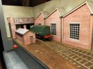
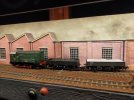
4mm London Road Sidings (formerly Poppy Lane)

Terry

Western Thunderer
I recently described on this forum how I turned a 4ft x 5.5 inch piece of mdf into a layout (of sorts!). It represented a roadside tramway and was basically a single piece of track running lengthways along the board. Named Poppy Lane, this is how it looked in all its glory..
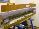
shunting plank 30 008.JPG

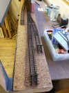
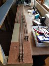
I eventually decided the time had come to scrap this effort. I salvaged all of the re-usable items and was preparing to retrieve the 2x1 framing for further use when my wife made a chance remark. Basically , she looked at the bare baseboard and asked, "Can't you do something with that?" Red rag to a bull! The challenge had been made and the glove thrown at my feet! I once again found myself looking at this..
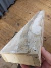
IMG20230110150516.jpg

I had a hankering to run one or two locos from my small diesel collection, so my thoughts turned to the possibility of modelling a small diesel refuelling point. Obviously the narrowness of the baseboard would have precluded a large installation but I reasoned that I should be able to fit in a couple of fuel tanks. I fired up my trusty Trax design program and played around until I came up with this plan:
IMG_20230110_0001.jpg
Terry
 
Last edited:
Terry

Western Thunderer
Basically two sidings with a single road fiddle yard. This will allow me to run a succession of different diesels to be refuelled and depart again. Another possible train movement would be a loco and two tank wagons arriving to refill the static fuel tanks.

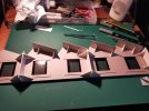
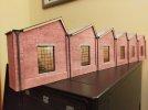
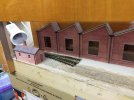
I thought that I would begin by building the low-relief building which runs for over half of the length of the scenic section. On the plan I have called it a loco shed but it could be a works of some sort. The building is there purely to present a background to the sidings and it's actual purpose is of no real consequence. I thought it would be interesting to have a varied roof line so I opted to use Scalescenes' North Light Engine Shed as the basis for the model. The actual Scalescenes' model is in full relief but I have only used one of the outside walls which is glued to 2mm greyboard No interior walls or other details were used, but I have used some bracing where appropriate.

This is how the building looked from behind with the roof partly constructed..

IMG20230110123359.jpg


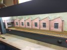
Front view of the completed building (or so I thought at the time!) I subsequently decided to replace the windows - more on this later.

IMG20230113175550.jpg


Terry
 

Terry

Western Thunderer
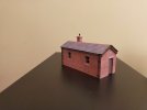
I then went on to construct the building on the far right of the plan above. The basis of this building is Scalescenes' Coal Office/Weighbridge which was extended lengthways by using parts from two kits.

Here's the result…

IMG20230122181753.jpg

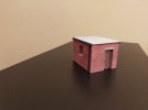
Having seen some photos on Google of fuelling points with small flat-roofed pump houses, I decided to have a go at making one. Once again I used Scalescenes' coal office/weighbridge as the starting point. I simply cut off the gable roof parts before construction and replaced the roof with a rectangle of card, coverered with Scalescenes'concrete sheet. I didn't include the interior walls and the rear was not detailed as it won't be seen. A Peco track pin provided the door knob.

IMG20230130173630.jpg

Terry
 

Terry

Western Thunderer
After some consideration, I came to the conclusion that the model would look better if the whole four feet of baseboard was given over to the scenic section. The 'off-stage' part would consist of a fiddle-stick to the left of the scenic section. This was constructied utilising the deck of one of the fiddle sticks previously used on Poppy Lane, with plywood sides glued thereon.

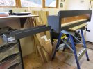
Attention was then given as to how the layout would be supported. I made two small support frames on which each end of the layout sits. Cross-braces keep them upright. In turn, these frames can stand on a typical village hall type six-foot table bringing the baseboard top up to a comfortable adult viewing height.

A lighting pelmet was fashioned using part of that which was attached to Poppy Lane and the original Poppy Lane backscene board was re-used.

At this point in the build the original track plan was giving me some concern in that all structures were placed against the backscene. I felt that more interest would be created if some structures were at the front of the baseboard. Accordingly, I reworked the track plan to give three sidings instead of the original two. This would allow the fuel tanks, pump house and office (now re-purposed as a staff bothy) to be situated at the front, with trains passing behind.

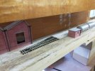
This photo shows the left-hand end beyond which the fiddle-stick would eventually be situated. A Scalescenes' girder bridge would eventually be placed at this end. I hoped that by placing the bothy as shown, it would help to mask the fiddle-stick and create more interest as trains pass behind. The right-hand point would create a short siding at the front ot the layout, which would end just before the pump house and fuel tanks. The straight road would lead to the second point with two sidings beyond.

IMG20230210152231.jpg


This is the right-hand end with the second point, it being left-handed. The straight road would be situated behind the storage tanks with the other short siding hard up against the backscene.

IMG20230210152238.jpg

Terry
 

Terry

Western Thunderer
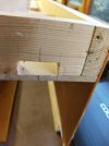
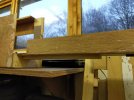
At this stage my attention was drawn to the problem of how to attach the fiddle-stick which was to be on the left-hand end of the layout, viewed from the front. The idea was to support the fiddle-stick on a strip of wood, which would pass through a hole in the baseboard end. I carefully drew the shape then drilled a number of holes, followed by cutting away material with a small saw. Files were used to take the wood back to my previously drawn pencil lines. The strip wood was a firm fit in the hole..

IMG20230212153854.jpg

I then constructed a small arch from three pieces of wood to accept the end of the strip of wood. Again, the strip of wood fits tightly in the hole created..

IMG20230212153935.jpg


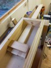
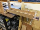
The strip of wood was given a liberal coating of 'Resin W' wood glue and the fiddle-stick was put in place. A number of small lengths of 2x1 wood were placed thereon to ensure the fiddle-stick was in good contact with the strip of wood, and all was left overnight to dry..

IMG20230212163621.jpg

IMG20230212163606.jpg

I decided to add small packing pieces of 2x1 to the base of the uprights supporting the lighting pelmet. This had the effect of bringing the pelmet forward to ensure that the lighting, once fitted, would light the very front of the layout.

At this stage the woodwork was given a coat of slate grey paint..

IMG20230216130850.jpg

Terry
 

Terry

Western Thunderer
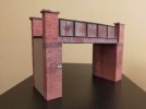
I had quite an enjoyable time constructing the plate girder bridge from the Scalescenes' kit. The bridge looks long but is in fact only 5.5 inches in length, this being the width of the baseboard..

IMG20230222221547.jpg

Terry
 
Last edited:
Terry

Western Thunderer
The whole of the baseboard surface was now covered with cork floor tiles. I intend to include a puddle or two on the baseboard surface, and my thinking was that it would be easier to dig away at the cork rather than the plywood baseboard. However, using the cork tiles had proved to be rather fortuitous as one of the two turnouts sits directly above the wooden support to which the fiddle-stick is attached. Said support effectively prevents any means of operating the turnout from below the baseboard. This was overcome by cutting a narrow channel in the cork and running the turnout operating rod along the top of the baseboard with a ninety degree bend taking the rod up through the hole in the centre of the stretcher bar. I envisaged that both turnouts would be operated from the front of the baseboard via push-pull rods, using large beads as the control knobs.

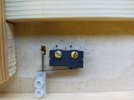
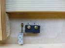
I decided to use micro-switches to change the turnout polarity. These are very cheap and effective, the only problem being the working out as to how they would be included in the linkage from the control knob to the turnout. In this case it proved remarkably simple. Let me explain. It proved necessary to make the operating rod in two pieces due to the number of bends required to get if from below the baseboard to the stretcher bar. I decided to use a terminal block to connect the two pieces of rod below the baseboard and realized that the plastic covering of the terminal block could be used to push the operating arm of the switch, thereby changing the polarity. The following photos will explain.

Switch open…

IMG20230324142649.jpg


Switch closed

IMG20230324142641.jpg

Note: in the pictures above, the brass rod passes beneath the operating arm of the switch. The white plastic casing is operating the switch.

Terry
 
Last edited:
Terry

Western Thunderer
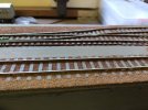
All track was laid and magnets were buried under the track on the three sidings to aid uncoupling of the rolling stock. All track is code 75 utilising Peco flat-bottom rail points and C&L track. Unfortunately, and without thinking of the unforseen consequences, I curved the two rear sidings away from the backscene. I ultimately discovered that I had left insufficient room to fit the fuel storage tanks at the front of the layout. Duh! This resulted in me having to lift and relay said sidings. I comfort myself with the knowledge that 'he who never made a mistake never made anything!' I painted the rail sides (and most of the running surface!), chairs and sleepers with Humbrol matt enamel No.186. This is a lovely shade of brown with a hint of red. If you look hard you can just make out the bar magnets buried beneath the sleepers..

IMG20230513194452.jpg

As the layout was to be DC operated, I decided to add an isolated section on each of the two longer sidings. I cut gaps in the appropriate rails and superglued a small piece of 20 thou styrene in each gap to prevent the rails moving together again.

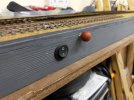
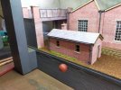
The wiring was completed and tested. I required a couple of rocker switches for the isolated sections on two of the sidings. I wanted to fit the switches on the front of the baseboard frame, the layout being operated from the front. I decided to fit some automotive dashboard rocker switches. Surprisingly, it was fairly easy to attach them to the 2 x 1 inch baseboard frame. I drilled a 20mm diameter hole completely through the frame and then filed a small area at 12 o'clock and 6 o'clock to clear the two projecting clips which are supposed to secure the switch to the rear of a thin panel. The switches were a tight fit which was sufficient to keep them in place. The two wires from the isolated track were then soldered to the projecting tags at the rear. I must say that the switches look very neat. The red ball is a bead, glued to the end of the turnout operating wire..IMG20230417210831.jpg


Coming up...ground cover.

Terry
 

Terry

Western Thunderer
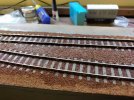
The thing which mainly stands out to me when viewing photos of the track in yards and sidings on the prototype railway, is that the track is normally buried to the tops of the sleepers. What to use for the ground cover? I looked around for something reasonably fine and preferably free. Enter the humble used tea bag! Yes those soggy brown things which you throw straight into the bin, or compost in my case.
I began by saving all of my used tea bags and laid them out in the sun to dry. I then invested 99p in a tea strainer. Every UK home had one of these at one time when loose tea was put in a teapot to brew. Of course, the use of tea bags has mostly done away with them.

I first experimented with tea bags some five decades ago to represent ballast on a small OO Gauge model. I used the tea straight from the dried tea bags and the result? Although a nice brown colour, It looked like the track had been ballasted with tea leaves! So, enter the aforementioned tea strainer. The contents of each tea bag was put through the strainer twice to remove the larger leaves. The resultant finer leaves and dust is what is goes onto the track.

Firstly, I decided to fill between the rails and on either side to the ends of the sleepers. I simply poured the tea onto the track and treated it much like the usual ballasts which we use. Once tidied up and removed from the sleeper tops, I sprayed the complete area with plain water.
I had already mixed an amount of PVA with water in a jam jar. I'm not precise about this. I just pour a big blob of PVA into the jar and add sufficient water to make it runny when stirred. This mixture was then applied to the track with a small pipette.

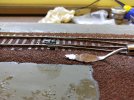
Once the diluted PVA has soaked in (just a few seconds), the tea becomes almost like a mash and can be smoothed and pushed into position with a suitable tool. I used a cheap palette knife bought as part of an artist's set from a stationary chain.

IMG20230620160921.jpg

The picture above shows the wet tea being smoothed. As I am using Peco Code 75 turnouts, which have thicker sleepers than the C&L track, the tea has been built-up to the sleeper tops. The turnout and track had been previously treated with the tea and were dry. In this photo I am adding the ground cover from the sleeper ends to the picture foreground.

Terry
 
Last edited:
Terry

Western Thunderer
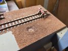
In some areas beside the plain C&L track I simply painted neat PVA onto the baseboard surface and sprinkled the tea thereon, leaving it overnight to dry. Once dry, any loose tea was vacuumed off. I noticed that when applying the tea by this method it remained a fairly uniform
light brown colour, as opposed to the darker colour which results when the tea has been soaked with the water spray and then had diluted PVA applied. Note the differing colours in this photo between the centre of the track and the area in the foreground. Both areas have dried. I prefer the darker colour as shown between the rails. I subsequently dribbled diluted PVA over the light brown areas to discolour same. Probably doubling the effort involved doing it this way, but I was in the process of experimentation.

IMG20230620162045.jpg

The areas between the tracks were covered using the 'mash' method..

IMG20230620163309.jpg

When the tea had dried, I tidied up by running a foam sanding block over the track surface to remove any tea leaves stuck to the sleeper tops and chairs, followed by the vacuum.

Terry
 

Terry

Western Thunderer
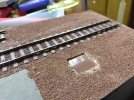
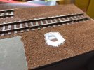
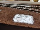
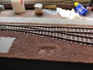
I wanted a change from the eternal summer with blue skies, much beloved by railway modellers. I was leaning towards painting an overcast sky, with the sound of a distant storm brewing (courtesy of a mini-speaker purchased a few years ago). I wanted to create the impression that we had already had a drop of rain and decided that a few puddles on the ground would be just the job. I used microscope slide covers measuring 18mm x 18mm. First, I laid the slide covers on the ground surface and drew around them with a pencil. I removed the tea leaves and cork to a depth which seemed suitable. One side of each slide cover was painted with an appropriate shade of enamel paint. When dry, each was laid in its hole on a bed of pva., painted side downwards. Ready-mixed plaster was built up around the edges of each slide cover and left to dry..

IMG20230630150604.jpg
IMG20230630151536.jpg

Tea leaves were stuck over the plaster..

IMG20230709175355.jpg
IMG20230630150612.jpg
IMG20230709175510.jpg

Since taking the photos I have added some darker tones around the puddles using very diluted black acrylic paint. At this point Peco buffer stops were superglued to the track at the end of the sidings.

Terry
 
Last edited:
Terry

Western Thunderer
I decided to install the lighting next. The word 'install' is a bit misleading as basically, I cut a short length of LED strip from the spool on which it came, peeled off the paper backing to reveal the sticky back, and simply pressed it into place. Total time taken in this task about two minutes! Great stuff this LED strip. I really would not revert to neon lamps, spotlights, etc. I buy the LED strip online on the usual auction site. It comes pre-wired to an on/off switch and 12v transformer plug. Here is the upturned layout showing the LED strip in place..

IMG20230717202600.jpg
Unfortunately, I chose to use 'cool white' which had the effect of making some of the Scalescenes' brickwork appear rather purple once the buildings were in place. It was a few minutes work to replace the LED strip with 'warm white' which showed an improvement.

Terry
 

Terry

Western Thunderer
I wanted to complete the backscene before adding the structures to the baseboard. The backscene board is basically a strip of plywood with two plywood end pieces. In order to get a suitable surface on which to paint, I covered the plywood with lining paper, bought from the wallpaper section of a chain store. The lining paper was fixed to the plywood with wallpaper paste and then a small roller was run over the surface to squeeze out any excess paste. When dry, the result was a perfectly flat surface with no air bubbles beneath. For this particular layout I wanted to produce a grey, sullen sky with dark threatening storm clouds approaching.

Out came the large, cheap tubes of acrylic paint, purchased from the usual chain stores for about £2 each. I used just three colours: white, black, and a minute amount of yellow ochre. Plain water was liberally painted onto the surface. White was mixed with a small drop of black to give a light grey, which was quickly painted on and dabbed in places with a piece of kitchen roll to create a cloud effect. Hard edges were softened by brushing on plain water. Whilst wet, small amounts of diluted black were added to the surface to give the impression of dark storm clouds, with a minute dab of yellow ochre added in places and brushed over with water to disperse it. Experimentation is very much the order of the day, leaning towards less rather than more. One important thing to remember. As you work your way along the surface to be painted, do not allow the edges of the painted area to dry as you will get a hard edge in your sky. I was working from left to right along the 4ft backscene, painting about sixteen inches at a time. As I was working, I kept an eye on the right side of the painted area, and kept painting water over the paint edges to prevent them from drying until I was ready to move onto that area.

Sadly, when the buildings are in place much of the sky won't be seen. However, this is merely a backdrop to create the atmosphere. Just as in the theatre, the action will be taking place downstage (towards the audience).

Right-hand end of the backscene.

IMG20230717202347.jpg


General view of the backscene. Subsequently, a hole was cut in the left-hand end to enable trains to access the fiddle-stick, and the corner joints were strengthened behind with aluminium angle.

IMG20230717202337.jpg

Terry
 

jonte

Western Thunderer
Very neat, Terry.

I do like your dried tea leaf idea for ballast. Suits the Peco track very well.

Jon
 

simond

Western Thunderer
The tea is an alternative to coffee grounds, of which I have an almost inexhaustible supply…. My fear is that the use of something organic might lead to undesirable things growing where perhaps imitation undergrowth might be more welcome..

I have since sieved soil from the garden, given it a good cooking (half an hour in a hot oven after the roast has been removed) and used that. It is also plentiful, and cheap!

I see the Wormshill model team have taken a similar approach.
 

Terry

Western Thunderer
Behind the scenes I was busily hacking about various Scalescenes' buildings to fit along the rear of the layout. As mentioned earlier in the 2nd post of this thread, I decided to change the windows in the building shown. I obtained some nice white screen-printed windows via Scalescenes' website, and backed them with black card. The white windows were given a wash of diluted black acrylic paint to tone them down.

I began to add the completed structures, working from the left-hand end of the layout..

IMG20230722124139.jpg


The bothy was glued in place and some weeds were added around the base. The photo appears to make the green colour much more vivid than in real life. This is the sort of detailing which I enjoy and adds so much to an otherwise ordinary scene.

IMG20230722134625.jpg


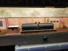
The fuel storage tanks, shown very early on, were sprayed black and mounted on a card base together with the previously constructed pump house. A brick bund was fitted around the tanks and the whole unit was glued in place at the front of the layout..

IMG20231109170859.jpg


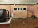
The office block is the Scalescenes' ARP signal box. I reduced its depth by cutting it lengthways, making it a low-relief structure. I added some interior details and a member of staff looking out over the yard.

IMG20231109171645.jpg

Terry
 
Last edited:
Terry

Western Thunderer
The tea is an alternative to coffee grounds, of which I have an almost inexhaustible supply…. My fear is that the use of something organic might lead to undesirable things growing where perhaps imitation undergrowth might be more welcome..

I have since sieved soil from the garden, given it a good cooking (half an hour in a hot oven after the roast has been removed) and used that. It is also plentiful, and cheap!

I see the Wormshill model team have taken a similar approach.
That's interesting Simon. I did wonder if I might eventually end up with a baseboard full of compost! I'll report back in due course if the worst happens. Thanks very much for your observations.

Terry
 

Terry

Western Thunderer
The ground cover was given a very diluted wash of black acrylic paint to give some variation of tone.
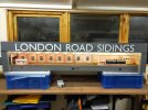
I realised that a succession of diesels arriving for refeulling and then just leaving might be a bit repetitive, so came to the conclusion the sidings could also be used for wagon storage, maybe Engineer's Dept. wagons. Accordingly, I have chosen a layout name to reflect this, as shown below. I would just point out that the lettering on the lighting pelmet is not distorted as shown in the photo. The self-adhesive lettering was obtained via the Internet and comes already formed into the words of your choice. Very useful and modestly priced. I did give the lettering a coat of varnish just to make sure it stays in place. As mentioned in post 4, small wooden frames have already been constructed to support the layout which will stand on a table for exhibtion purposes. Testing the fiddlestick with locos has made me aware that some support may be required at the far end. I'll give this some attention shortly.

IMG20231109170811.jpg


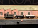
I am now in the process of fitting some of the finer scenic details to bring the layout to life. Meanwhile, here are a few photos to give you a flavour of how things might look..

IMG20231109171011.jpg
IMG20231109172556.jpg
IMG20231109172441.jpg

Terry
 
Top