You are using an out of date browser. It may not display this or other websites correctly.
You should upgrade or use an alternative browser.
You should upgrade or use an alternative browser.
7mm Lochmaben, a new layout.
- Thread starter OzzyO
- Start date
OzzyO
Western Thunderer
Hello all,
starting work on the last point on the front of the layout, it's in the back ground with the crossover in the foreground.

The pint is almost finished with both closer rails in place but I'm not sure if they are fastened down. The Vee is fixed in place. If not the one with the track gauges on it is getting fixed down.

Just about the same shot from my drone.

It's all plain track from now on so it should be plain sailing????
After that it's going to be making the turnout operating units for the points on the front, then adding all of the interesting bits to the points and the cosmetic fishplates.
What could go wrong?
ATB
OzzyO.
starting work on the last point on the front of the layout, it's in the back ground with the crossover in the foreground.
The pint is almost finished with both closer rails in place but I'm not sure if they are fastened down. The Vee is fixed in place. If not the one with the track gauges on it is getting fixed down.
Just about the same shot from my drone.
It's all plain track from now on so it should be plain sailing????
After that it's going to be making the turnout operating units for the points on the front, then adding all of the interesting bits to the points and the cosmetic fishplates.
What could go wrong?
ATB
OzzyO.
OzzyO
Western Thunderer
Hello all,
track laying is going on at my high (don't snails go fast) speed, but I have not taken any photos of my new track.
But now for something completely different (that could be a good line in the start of a show). Electrical Edwards has been doing his stuff underneath the base boards, using blue for J and brown for K the two "feed" wires for the DCC power. The green wires are for the common crossings and go to an electrical gismo that sets the routes (don't ask me how as I don't have a scooby do how it works).
Yes that is a standard kettle connector in the bottom of the base board we use them for taking J and K and one other feed over the BBJs in this case I think that it's going to be the wire from the point vees (but I could be wrong?).

In this photo you get a bit better view of the cross bracing on the scenic board in the background.

I've been looking at how to throw the two cross over points that are near to one of the angled cross braces and came up with this. The idea is that the point blade will have an inverted L piece of N/S wire soldered to the inside of the end going through holes in the base board top and into tubes that are soldered to the long piece of copper clad and a rod will run from one end of the C/C to the TOU. The C/C still has to be gapped and the position of the tubes determined.

From the back I have used a length of C section brass channel to add strength, the lengths of brass wire are just to try and avoid any twist in the unit.

When I was soldering the short sections of C section on the front of the unit I used these, ceramic tipped tweezers. Three different ends to the tweezers for about £7.00 from you know where.

ATB
OzzyO.
PS, now onto a fun job underlining my new combine.
track laying is going on at my high (don't snails go fast) speed, but I have not taken any photos of my new track.
But now for something completely different (that could be a good line in the start of a show). Electrical Edwards has been doing his stuff underneath the base boards, using blue for J and brown for K the two "feed" wires for the DCC power. The green wires are for the common crossings and go to an electrical gismo that sets the routes (don't ask me how as I don't have a scooby do how it works).
Yes that is a standard kettle connector in the bottom of the base board we use them for taking J and K and one other feed over the BBJs in this case I think that it's going to be the wire from the point vees (but I could be wrong?).
In this photo you get a bit better view of the cross bracing on the scenic board in the background.
I've been looking at how to throw the two cross over points that are near to one of the angled cross braces and came up with this. The idea is that the point blade will have an inverted L piece of N/S wire soldered to the inside of the end going through holes in the base board top and into tubes that are soldered to the long piece of copper clad and a rod will run from one end of the C/C to the TOU. The C/C still has to be gapped and the position of the tubes determined.
From the back I have used a length of C section brass channel to add strength, the lengths of brass wire are just to try and avoid any twist in the unit.
When I was soldering the short sections of C section on the front of the unit I used these, ceramic tipped tweezers. Three different ends to the tweezers for about £7.00 from you know where.
ATB
OzzyO.
PS, now onto a fun job underlining my new combine.
Last edited:
OzzyO
Western Thunderer
Hello all,
I really should have put this in my last post but I forgot to.
It's to do with something a bit smaller than the track laying but as important in its own right, it's the ground (shunting) signals. We have two options for these.
The MSE ones that we have some of, as shown below.

Or the ones from Bolton Bits as shown below.

I quite like the look of both of them. We will want them to work, so which way to go? But not 'lit' as what's the point when the layout is set in daylight?
ATB
OzzyO.
I really should have put this in my last post but I forgot to.
It's to do with something a bit smaller than the track laying but as important in its own right, it's the ground (shunting) signals. We have two options for these.
The MSE ones that we have some of, as shown below.
Or the ones from Bolton Bits as shown below.
I quite like the look of both of them. We will want them to work, so which way to go? But not 'lit' as what's the point when the layout is set in daylight?
ATB
OzzyO.
Last edited:
MarkR
Western Thunderer
Hi OzzyO,I used these, ceramic tipped tweezers. Three different ends to the tweezers for about £7.00 from you know where.

I quite like the look of those tweezers, but having looked "you know where" I can't find them! Perhaps I am looking at the wrong "you know where"!
Do you have a link?
Many thanks.
Mark
OzzyO
Western Thunderer
Hi Mark,Hi OzzyO,
I quite like the look of those tweezers, but having looked "you know where" I can't find them! Perhaps I am looking at the wrong "you know where"!
Do you have a link?
Many thanks.
Mark
if this link works it should hep you a bit.

Stainless Steel White Ceramic Tweezers For Electronics Soldering Repair Tools UK | eBay
Find many great new & used options and get the best deals for Stainless Steel White Ceramic Tweezers For Electronics Soldering Repair Tools UK at the best online prices at eBay! Free delivery for many products.
www.ebay.co.uk
HTH
OzzyO.
Ps. then go to type and ask for a set of three, looks like the price has gone up a bit.
Last edited:
Bill Campbell
Western Thunderer
Hi OzzyOHello all,
I really should have put this in my last post but I forgot to.
It's to do with something a bit smaller than the track laying but as important in its own right, it's the ground (shunting) signals. We have two options for these.
The MSE ones that we have some of, as shown below.
Or the ones from Bolton Bits as shown below.
I quite like the look of both of them. We will want them to work, so which way to go? But not lit as what's the point when the layout is set in daylight?
ATB
OzzyO.
I have used the MSE kits for my layout and made them operational by modifying the back blinder to take an operating wire from sub-baseboard.

This, however was a fudge as the MSE kit does not lend itself well to operation. I have recently been making up some non-operational versions and the quality of the metal used for the castings left something to be desired - tricky to solder with 70 degree solder and I would not like to try a higher temperature solder.
From the look of the fret I think the Bolton's Bits version will be easier to make operational as there are some nice holes for a linkage in the balance weight arm.
Regards.
OzzyO
Western Thunderer
Hi OzzyO
I have used the MSE kits for my layout and made them operational by modifying the back blinder to take an operating wire from sub-baseboard.
View attachment 166411
This, however was a fudge as the MSE kit does not lend itself well to operation. I have recently been making up some non-operational versions and the quality of the metal used for the castings left something to be desired - tricky to solder with 70 degree solder and I would not like to try a higher temperature solder.
From the look of the fret I think the Bolton's Bits version will be easier to make operational as there are some nice holes for a linkage in the balance weight arm.
Regards.
Hello Bill,
do you have a photo of the ground signal from the side?
TFAH
OzzyO.
simond
Western Thunderer
I like lit signals, even if the layout is set in / displayed in daylight. Looking down the line…
Jon’s kits are designed to work, he has an active thread in t’other place, you can see how he does it. Very small servos.
Whilst I habitually use red & blacK for J&K, (with black to the back) I’m pleased to hear that the common crossing connections are green. Frogs are obviously green") .
.
Coming along very nicely!
Jon’s kits are designed to work, he has an active thread in t’other place, you can see how he does it. Very small servos.
Whilst I habitually use red & blacK for J&K, (with black to the back) I’m pleased to hear that the common crossing connections are green. Frogs are obviously green
. Coming along very nicely!
Bill Campbell
Western Thunderer
I will try to remember and take one (or more) tomorrow.Hello Bill,
do you have a photo of the ground signal from the side?
TFAH
OzzyO.
Regards.
OzzyO
Western Thunderer
I like lit signals, even if the layout is set in / displayed in daylight. Looking down the line…
Jon’s kits are designed to work, he has an active thread in t’other place, you can see how he does it. Very small servos.
Whilst I habitually use red & blacK for J&K, (with black to the back) I’m pleased to hear that the common crossing connections are green. Frogs are obviously green
Coming along very nicely!
Hello Simond,
never thought of it that way, it's just that the kettle connectors that we use for across the BBJs have blue brown and green and yellow. So it just seemed obvious to keep using the same colours (or nearly the same).
ATB
OzzyO.
Bill Campbell
Western Thunderer
As requested - photos of MSE ground signals. Apologies for the dust on some of them - didn't notice until I saw the photos on my monitor.
The balance weights on the finished models are not connected to the operating mechanism - access to the end of the balance weight crank in the base of the signals is very restricted. The Bolton's Bits version looks a lot better in this respect.
One of the awkward aspects of the MSE kits is the necessity to drill the castings for the disc and balance weight spindles - care and patience are required. There is not much material to drill the holes for the balance weight spindle - the last 2 photos of a double unit under construction give a view of this. The units under construction will not be made to operate.


Regards.
The balance weights on the finished models are not connected to the operating mechanism - access to the end of the balance weight crank in the base of the signals is very restricted. The Bolton's Bits version looks a lot better in this respect.
One of the awkward aspects of the MSE kits is the necessity to drill the castings for the disc and balance weight spindles - care and patience are required. There is not much material to drill the holes for the balance weight spindle - the last 2 photos of a double unit under construction give a view of this. The units under construction will not be made to operate.
Regards.
OzzyO
Western Thunderer
Hello all,
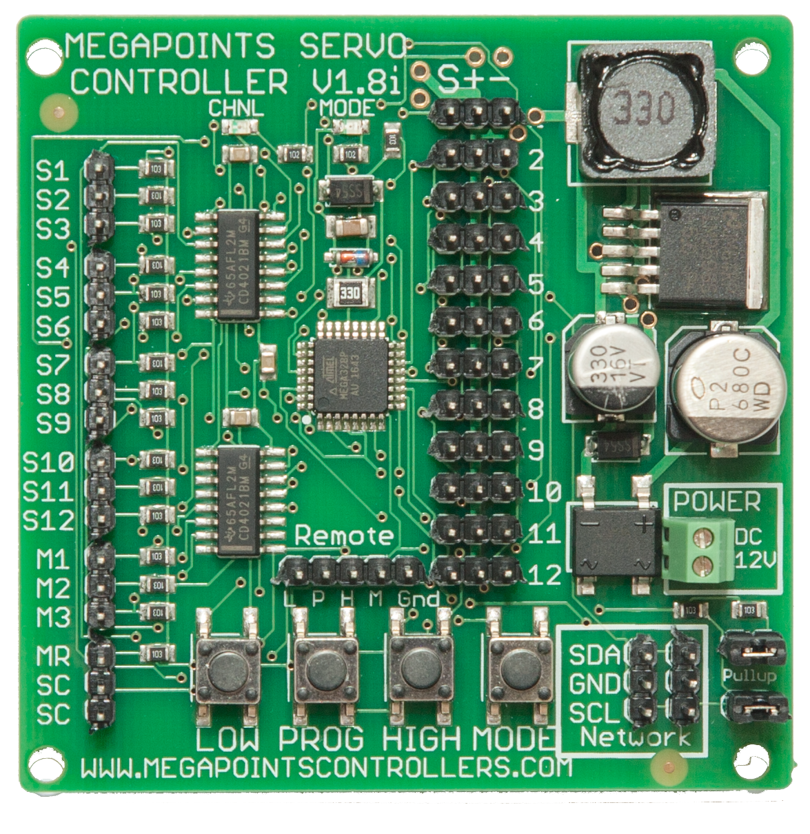
as I'm off track laying on this thread at the moment I thought that I'd show you some gizmos that electrical Edwards has got. If I've got this correct these are for route setting so with the input of one code say R4N (road 4 north). These gizmos will set the points and point vees to the correct road and power supply.
First the warning.

One of the units and the waning.

It looks like he's got two sizes of units, this one could be for the front as we only have four points and six signals.

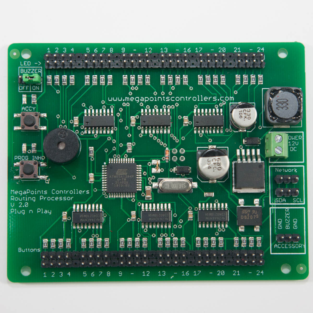
This size could be for the fiddle yard as we have about twenty points in it, some times you may have to throw up to five points to set one road. There will be at least two of them in the yard one for the north end and one for the south end (or up and down).

For the power I think that we will be using a dedicated transformer one for the point gizmos and one or two for the DCC units.
If you have any question, I'll have to pass them on to electrical Edwards.
ATB
OzzyO.
as I'm off track laying on this thread at the moment I thought that I'd show you some gizmos that electrical Edwards has got. If I've got this correct these are for route setting so with the input of one code say R4N (road 4 north). These gizmos will set the points and point vees to the correct road and power supply.
First the warning.
One of the units and the waning.
It looks like he's got two sizes of units, this one could be for the front as we only have four points and six signals.
This size could be for the fiddle yard as we have about twenty points in it, some times you may have to throw up to five points to set one road. There will be at least two of them in the yard one for the north end and one for the south end (or up and down).
For the power I think that we will be using a dedicated transformer one for the point gizmos and one or two for the DCC units.
If you have any question, I'll have to pass them on to electrical Edwards.
ATB
OzzyO.
OzzyO
Western Thunderer
Hello all,
if these links work it should tell you a lot more.
 megapointscontrollers.co.uk
 megapointscontrollers.co.uk
I think that they are the things that electrical Edwards has got?
But I could be very wrong, all of the lads know that if it has more than two wires I'm up a creek that has a very brown colour to it.
ATB
OzzyO.
if these links work it should tell you a lot more.
Servo Controller (12)
Our flagship Classic-range servo board, controlling up to 12 R/C servos for points and semaphore signals. Each channel has its own end points, speed and direction, with smooth semaphore bounce and…
megapointscontrollers.co.uk
Route Processor
Sets a whole route at the press of a single button, then keeps watch over it. Store up to 24 routes of up to 192 devices each, with a built-in alarm that sounds if an active route is disturbed.
megapointscontrollers.co.uk
I think that they are the things that electrical Edwards has got?
But I could be very wrong, all of the lads know that if it has more than two wires I'm up a creek that has a very brown colour to it.
ATB
OzzyO.
OzzyO
Western Thunderer
Hello all,
I'm after some advice on some of the signals for Lochmaben, I'm using a signal box diagram for Haverthwaite as the base for our signals.
Any thing to the left of the bridge is not being modelled.

Now to the questions. Signal 4 is the platform starter with co-acting arms, I'm OK with that.
Signal 4s is used for the train to draw ahead to clear points 10 and the FPL 9 and set back into the second platform to then draw ahead using signal 6. So should signal 4s be a subsidiary arm or a ground signal. also should we have a ground signal by FPL 9?
Coming back out of the yard we draw ahead until passed point 11and wait for ground signal 15 to be pulled off and set back into the platform, change points and wait for signal 5 to be pulled off. Then it either off up the line or set back onto the rest of the train in the platform.
Signal 17 is going be a bracket just to add something to the station area.
There is another way this area could be signalled. You would have a ground signal before the point that is off scene to the left and run straight on to the head shunt (so signal 6 would not be needed). But you could not split your train in the platform as this would block the platform road on the wrong line, and the line is not signalled for that type of running.
Thanks for any help,
OzzyO.
OzzyO
Western Thunderer
Hello all,
Electrical Edwards and me went up the club on Saturday for a few hours Ian started to put the green boards in place and I moved my base boards about a bit.
Last night Electrical Edwards got all of the green boards in place and wired up, but when he came to try moving a servo nothing or it would not do what he wanted so after he had pulled out more hair (not that he's got much to start with). It turned out that a blob of solder was bridging the gap between two of the terminals on the servo, so a new servo was installed and we had lift off.
Trying to photo flashing lights is not a fun sport. The part in the aluminium channel section with the micro switch on is one of our point operating units (the one that worked).

After all the fun and excitement of the electrical bits on to some thing like normal (less of that in the back of the class). We dropped the baseboard that has the main cross over and one of the yard points on it. This is the board that is left with some of the last bit of track to be laid on the whole layout.

It was then time to move this board so we could get the last board in its place. This board is the last of the scenic boards and it also connects on to the fiddle yard (that bit of track was laid a bit back). So it's onto cutting rail to fit the gaps, then onto fitting fishplates and all of the details to the points and the TOU to each point. So a good bit of work still to do.

ATB
OzzyO.
PS keep smiling it makes them think what has he been up to?
Electrical Edwards and me went up the club on Saturday for a few hours Ian started to put the green boards in place and I moved my base boards about a bit.
Last night Electrical Edwards got all of the green boards in place and wired up, but when he came to try moving a servo nothing or it would not do what he wanted so after he had pulled out more hair (not that he's got much to start with). It turned out that a blob of solder was bridging the gap between two of the terminals on the servo, so a new servo was installed and we had lift off.
Trying to photo flashing lights is not a fun sport. The part in the aluminium channel section with the micro switch on is one of our point operating units (the one that worked).
After all the fun and excitement of the electrical bits on to some thing like normal (less of that in the back of the class). We dropped the baseboard that has the main cross over and one of the yard points on it. This is the board that is left with some of the last bit of track to be laid on the whole layout.
It was then time to move this board so we could get the last board in its place. This board is the last of the scenic boards and it also connects on to the fiddle yard (that bit of track was laid a bit back). So it's onto cutting rail to fit the gaps, then onto fitting fishplates and all of the details to the points and the TOU to each point. So a good bit of work still to do.
ATB
OzzyO.
PS keep smiling it makes them think what has he been up to?
Last edited:
OzzyO
Western Thunderer
Hello all,
just a quick update on the layout, first all of the main lines are now in place.

The next bit to get attacked is the yard. Road four is now all in place, numbered from R - L.

The next one to get attacked will be road three, then that will be all of the track laid on the whole layout. Then it's onto all of the track details like fish plates packing blocks on the points etc.

I also received these from Wizard Models today for Kev to have a play with.


ATB
OzzyO.
just a quick update on the layout, first all of the main lines are now in place.
The next bit to get attacked is the yard. Road four is now all in place, numbered from R - L.
The next one to get attacked will be road three, then that will be all of the track laid on the whole layout. Then it's onto all of the track details like fish plates packing blocks on the points etc.
I also received these from Wizard Models today for Kev to have a play with.
ATB
OzzyO.
Pencarrow
Western Thunderer
Top tip... Put something hard to drill through between the underside of the baseboard and the Megapoints circuit board. They don't take kindly to being drilled through when installing level crossing gates... Ask me how I know!Hello all,
as I'm off track laying on this thread at the moment I thought that I'd show you some gizmos that electrical Edwards has got. If I've got this correct these are for route setting so with the input of one code say R4N (road 4 north). These gizmos will set the points and point vees to the correct road and power supply.
First the warning.
View attachment 166684
One of the units and the waning.
View attachment 166687
It looks like he's got two sizes of units, this one could be for the front as we only have four points and six signals.
View attachment 166685
This size could be for the fiddle yard as we have about twenty points in it, some times you may have to throw up to five points to set one road. There will be at least two of them in the yard one for the north end and one for the south end (or up and down).
View attachment 166686
For the power I think that we will be using a dedicated transformer one for the point gizmos and one or two for the DCC units.
If you have any question, I'll have to pass them on to electrical Edwards.
ATB
OzzyO.
You may well think you couldn't possibly drill through from above as it's obvious the circuit boards are there, particularly after carefully noting where the gate posts will go but...
Oh, and drilling through them voids the warranty and Megapoints don't do repairs.

Last edited: