Lathes and M/C tools.

OzzyO

Western Thunderer
Hello all,

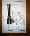
setting up the "bearing block" for the cross slide. I'm quit happy at how its set up in the four jaw chuck to only get .015 (0.00059") over the length approx. 3.7"
Turning it was a bit bang bang until I got to the full face (it doesn't help that the head bearings are on the way out).
IMG_0242.JPGIMG_0243.JPG

The next job is to drill the mounting holes, then to set it back up in the lathe and drill and bore the centre hole and the recess for the front thrust bearing.

An update on the cost.
Leadscrew £27.12 (this is for 1 meter I only wanted approx. 350mm).
Leadscrew nuts X3 £2.59.
Thrust bearings X 2 £2.35
Grease nipple (modification) £0.99
Total. £33.05
A lot better than my first estimate.

ATB

OzzyO.
 

OzzyO

Western Thunderer
Hello Rob, all,

these are the places that I'm getting my parts from. I don't know if the links will work as I did this as a screenshot. You can get the leadscrew in shorter lengths from other suppliers, but I needed over 300mm in length.
1716887980461.png

I have now M/Cd the counter bores for the thrust bearings, with a bit of luck and a fair wind I'll have the bearing block finished to-day.
Then it's just waiting for the bits to turn up. But I can always start work on the cross slide scale, it's going to be fun!!

ATB

OzzyO.
 
Last edited:

OzzyO

Western Thunderer
Hello all,

back to the bearing block, all of the turning is done. This photo shows the state of the finish of the outside of the tube. I did say that the head bearing are on the way out, I'm not going to start on them until I get are of the work completed on the mill.
IMG_0245.JPG

The outside of the bearing block you can see how the rebate is for a finish.
IMG_0249.JPG

Showing the hole for the grease nipple. If your thinking that is off centre why?
IMG_0256.JPG

With the grease nipple and back part of the bearing in place,
IMG_0258.JPG

and with the roller balls in place, now you can see why the hole is where it is.
IMG_0259.JPG

Setting up the rectangle for turning for the outside dia.
If you have not seen this way of setting up a job in a lathe.
1) first you mark out the centre of the job and centre pop it.
2) then you get two centres (if doesn't matter if the one in the tailstock is a running centre) then mount another centre between the centre and the pop mark in the job.
3) Set up your magnetic stand and (clock) D.T.I. then set it up until the D.T.I. is at zero.
IMG_0250.JPG
IMG_0251.JPG

You can see what I use for keeping the chuck key near to the M/C . It's a retractable fastening for I.D. passes. You can get 5 for about £1.00.
IMG_0252.JPG

I have decide that my first idea was a bit naf, that was rebating a nut in to the leadscrew nut. But as I'm now making the leadscrew nut out of brass why not just tap it, more so when I saw these for £6.00 for H.S.S. at just about twice the price of three nuts.
1717071617628.png
ATB

OzzyO.
 
Last edited:

OzzyO

Western Thunderer
Hello all,

not that much to say today.
The first job after my last post was to part-off the rectangular part of the brass block after I had turned the outside dimensions. I used this for the first time on this job and what a joy to use, the letters are the type of tool the numbers are size of tool bar so 10X10mm the last one the width of tip so 2mm.
IMG_0261.JPG

One of the parted off pieces nice and clean, A bit of a curve where the blade was only cutting on one side.
IMG_0267.JPG

Turning the bore, I did make a mistake in setting the job up in that I had one of the dogs so far out I was getting a bit of vibration.
IMG_0266.JPG
IMG_0268.JPG

This was where it all went wrong I was aiming at 14mm and I ended up at near a 15mm I tapped it just to see how it would look. Well it ran down the screw but it only had half the thread in place, so how long it would last?
Now I have two options one to make a new one from scratch, a lot of work. Two, sleeve the bore so I'm going this way with a 17mm o/d tube that has a 14mm i/d bore. If I make a mess of that I could re-bore it to 18mm and use a 18mm o/d tube that has a 14mm i/d.
I also turned the dog that was sticking out a lot, around.
IMG_0269.JPG

ATB

OzzyO.
 

OzzyO

Western Thunderer
Hello all,

the lead screw nut after tapping M16L/H, it took a lot more grunt to do it than I though it would do.
IMG_0274.JPG

The lead screw turned to 10mm and M8, I've yet to die nut the M8 thread,
IMG_0273.JPG

Checking the fit of the cap on the end of the lead screw and the first thrust bearing,
IMG_0275.JPG


The make of the thrust bearing,
IMG_0276.JPG

All of the parts up to the end cap in place,
IMG_0277.JPG

All the parts in place, the index wheel is held in place by a grub screw,
IMG_0278.JPG

The m8 screw thread die nutted on the end of the lead screw,
IMG_0280.JPGIMG_0281.JPG

All of the parts in place with a nut holding them in place,
IMG_0283.JPG

I have yet to cut the end of the screw to the correct length for a extra-long nut and a short grub screw.
IMG_0282.JPG

Not that much more to do on the lead screw.

ATB

OzzyO.
 

simond

Western Thunderer
Ozzy,

It looks like you’re using a conventional (60 degree?) thread form - I’d have expected a buttress/trapezoidal thread, as they’re stronger and lower friction. Was it simply easier this way, or was there another reason?

I will need to do a similar job on my lathe cross-slide at some point, and had intended to buy a leadscrew and nut.

This sort of thing:

atb
Simon
 

OzzyO

Western Thunderer
Ozzy,

It looks like you’re using a conventional (60 degree?) thread form - I’d have expected a buttress/trapezoidal thread, as they’re stronger and lower friction. Was it simply easier this way, or was there another reason?

I will need to do a similar job on my lathe cross-slide at some point, and had intended to buy a leadscrew and nut.

This sort of thing:

atb
Simon
Hello Simon,

I'll hold my hand up, I didn't know that you could buy buttress threads and nuts off the shelf but the price is a bit off putting.
M16X2X350 L/H £37.00 Lead screw.
M16 L/H nut £14.90.
So just for the parts £51.90

My parts M16X2X1000 L/H lead screw £27.00
M16 L/H tap and die £6.00
Total, £33.00.

So a saving of £18.90

Yes it would have been nice to use a buttress thread. But!!!!

Keeping on with the lead screw, I have used this photo before. I have yet to cut the end of the screw to the correct length for a extra-long nut and a short grub screw. Can you see what's going on in the background?
IMG_0292.JPG

The two leadscrews' above and below, the old one at the top. I could be tempted to add a dial pointer using the grease nipple to fasten it down. The dial on the new hand wheel has 200 divisions on it so 0.01, but as I'm fitting a d.r.o. what would be the point?
IMG_0293.JPG

ATB

OzzyO.
 

OzzyO

Western Thunderer
Hello all,

after all of the turning on the leadscrew the old DRO became very unreliable so I thought I'd start looking at fitting a proper D.R.O. The first job was taking the old one off and then drilling and tapping the holes for the new one. The tapped holes in the saddle number from the L/H end No 1 & 4 were for the old DRO number 2 & 3 are for the new reading head. On the cross slide the holes in the vertical face are for the mountings for the D.R.O. scale. The two on the top face were for the old DRO.
IMG_0284.JPG

The two mounting brackets for the D.R.O. are in place on the vertical face. Along with the mounting bracket for the reading head.
IMG_0285.JPG

Fitting the first part of the cutting (swarth) guard, (more on that latter).
IMG_0286.JPG
IMG_0287.JPG
IMG_0287.JPG

Test fitting the D.R.O. for size this was when I found two problems.
The first one is that its too high above the top of the cross-slide and the compound slide could not rotate.
The second one is that the reading head bracket is not deep enough from the cross slide.
IMG_0288.JPG

IMG_0289.JPG

IMG_0290.JPG


For the cross slide I decided to buy a UM1 scale, only about £14.00 more than a UM5 scale. My logic is that you have to divide the amount that your taking off by 2. I may be wrong in my logic in that you maybe able to do the division on the read out.

ATB

OzzyO.
 

David Waite

Western Thunderer
If it was me I would just read the amount in either metric or imperial as you would on a manual dial
I think there will be less confusion in other words read one thou / cut one thou which is two off the diameter , the reason I say this is as a apprentice we had one large lathe that on the cross slide its scale read off the diameter so dialing up one thou on the scale cut exactly one thou of the diameter ie the cutter moved only half a thou, I always had to keep my wits about me as it was so easy to make a mistake and I did once from then on it always worried me that I might do it again, I don’t know why this particular lathe was done this way, it just wasn’t normal a bad design in my book.
David.
 

OzzyO

Western Thunderer
Hello David,

after working on mills for a good part of my life one thou equalled one thou off the job. so to have a lath that takes one thou off when you have moved the cross slide one thou, is a lot better in my eyes. Rather than having to divide your cut in half all of the time. more so when the compound slid is turned to 90 deg. one thou is one thou the same as the longitudinal hand wheel.

ATB

OzzyO.
 

simond

Western Thunderer
Interesting question.

I asked our production manager, who is half my age, but who has made his career in, and has a wealth of experience of, CNC machining for his opinion.

We have two Doosan Lynx mill-turn machines, which, when they are turning, they do “increment on diameter”, ie a millimetre off diameter is half a millimetre movement of the tool, and when they are milling, they do “a millimetre is a millimetre”

This is quite easy to arrange in a whopping great FANUC controlled machine, but less obvious in a hobby lathe, if it’s used for milling as well as turning.

If it only gets used for turning, then I’d go for the DRO giving you the diameter.

atb
Simon
 

David Waite

Western Thunderer
Hello David,

after working on mills for a good part of my life one thou equalled one thou off the job. so to have a lath that takes one thou off when you have moved the cross slide one thou, is a lot better in my eyes. Rather than having to divide your cut in half all of the time. more so when the compound slid is turned to 90 deg. one thou is one thou the same as the longitudinal hand wheel.

ATB

OzzyO.
I was thinking when I wrote the reply you may have been wanting it to be simpler to a mill cut, for me it is the other way around and lathe work was more of what I did compared to milling so halving is just second nature, it’s surprising how we each have our own likes and dislikes of how a type of machinery works and is set up and also how we go about machining a component, even though we were taught similar basics.
David.
 
Top