7mm GWR Oil Burners

pete waterman

Western Thunderer
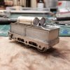
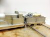
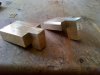
I have been trying to get a kit out for a long time for the GWR Oil Burners . At last I've started I have done the etches for the 3500 Gall tank and the 4000 Gall tank. I have had a set of drawings for more years than I care to own up to. But and there's always a But with the GWR there are no drawings for the 4000 Gall tender and photos show lots of minor differences. So here's a plea for info. I would guess that there had to be a walkway on the tender top! and that would mean a ladder from the tender floor this looks only to be on the 4000 tender as the 3500 fills from below or the rear but the 4000 fill around the middle of the tank even this moves !some photos its in the middle some forward of the middle. I would say this was done after a few went in to service. Do you have photos of the tender or drawingsSANY0007.JPG
 

Steph Dale

Western Thunderer
I've got the same problem with a Southern oil burner I'd like to do; no high level rear views I can find.
I know there's two ruddy great brackets anchoring the oil tank to the water deck plate; but I've got no real idea what the blighters look like...!

Steph
 

pete waterman

Western Thunderer
Looking at the Castle back plate and then looking at the 28XXs on the film you will see that the controls look slightly different. So does any one have a photo of the 28xx back plate.
 

pete waterman

Western Thunderer
Ok the auxiliary steam valve is in a different place on the Castle its the valve on the left above this is because the heater must be in a different place as the feeds are on the right hand side and on the 28XX are on the left. The oil flow regulator is far more to the left on the 28XX. I have worked this out from viewing the drawing against the photo of the Castle cab there is all so another question what is the stand in the very left hand corner of the Castle cab it looks like a Oil flow regulator but that the thing with the lamp shade over the top this was a light for the fireman to see the dial so he can adjust the flow. One question that has been answered is that oil feed to the tank is on both sides of the tender something I could see in lots of photos.
 

Steph Dale

Western Thunderer
Pete,
There was an article on the '47 oil burning scheme in an old British Railways Illustrated, which had some very useful photos. Unfortunately with no meaningful (searchable) on-line index I've not been able to find out which one. Which is infuriating as I've almost certainly got a copy here.
Steph
 

flexible_coupling

Western Thunderer
Believe it or not, I have a copy of that very magazine in my hand Steph. The owner of my shop has a huge hoard of boxes of new back-issues of BRI, and we literally give them away. I'll scan it for you tomorrow if need be :)

Edit: If you are in a hunting mood, it's January 1995's issue, Vol. 4 No. 4.
 

mickoo

Western Thunderer
I have, have them all bar the last few this year, they're about the best resource for BR steam / diesel modeling I can think of. Can also scan if required once I dig that copy out, knowing BRILL there'll probably be other articles as well just takes an age to flick through several hundred mags lol.
 

Steph Dale

Western Thunderer
Pete,
It's views with the rear brackets that are difficult to obtain. There are two brackets on the back of the oil bunker which fit to the tender water deck. As you can imagine you need a pretty high rear view to see over the tender coping and I've comprehensively failed to find the view needed.
Steph
 
Top