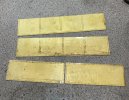
Freelance early steel wagon

Jon Nazareth

Western Thunderer
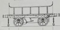
I have some spare tender etches from the Jennifer Who project so, I decided to make them up into a wagon. It’s going to be very loosely based on the early curved end LNWR wagon designed by Henry H Henson. It would have been nice to have had the curved ends but that seemed like a bridge too far for my limited skills.
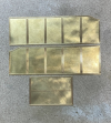
The tender sides are 57mm high but I’ve reduced this for the wagon to 29mm. The photos show the before and after with the etches and, if I get time, I’ll start drilling out for the rivets, I’ve ordered more, this afternoon. I’m thinking of using angle sections in the corners and to make any sense of them, I’m going to have to have rivets or the appearance of rivets showing on the inside. I have a few ideas, not sure if they’ll work, but I’m hoping that more will come in time . I used soldered angle in the corners of the tender but they are tucked away inside the tank and can’t be seen. Very early days with this build.

Jon
IMG_3612.jpeg
This is the Henson wagon that I’m basing my effort on.

IMG_0160.png
Full height tender sides.

IMG_3609.jpeg
Sides cut down to 29mm.
 
Last edited:

Osgood

Western Thunderer
I like the curved corners of the Henson wagon with the transition to higher ends -possibly 18” radius?
 

NickB

Western Thunderer
The curved corners would really make this wagon stand out in the crowd. I don't think they are as bad as they might appear at first sight. I think it's reasonable to assume that the flat bits of the ends between the corners are separate plates so that there would be vertical straps with double rows of rivets there, as for the sides. In that case, I would make each side with two corners in the flat, complete with all the riveted straps, then bend the corners. Use a flat piece at each end to join them together, and conceal the joins behind riveted strips.

Jon, you are probably too far on to change course now so I'll leave it there. I'm sure the final result, with or without curved corners, will look as spendid as the tender does.

Nick
 

Jon Nazareth

Western Thunderer
Nick
Yes, you are right there, too far along the road now to change. I did think about building curved ends but I felt sure that I couldn’t keep all square once the bends were put in. Maybe another time.
I’ve attached a picture of the end view for anyone interested.

Jon

P.S. I was going to drill lengths of angle and rivet them into the corners therefore holding therefore holding the two sides and two ends together. I can’t do that now as the holes in those sides and ends are too close to their edges and I wouldn’t easily be able to peen over the ends of the rivets. Now, my thoughts are to simply solder the angles and leave it at that. It’s all a bit of a bummer as I did want rivets showing on the inside even if only peened over ones.

IMG_3614.jpeg
 
Last edited:

Jon Nazareth

Western Thunderer
An aside.
While drilling holes and de-burring them, my mind started to wander noticing the ‘off-cuts’ from the cutting down of the tender etches. My, I thought to myself, they would make another wagon. It would have sides something in the region of 25mm high but would still be a mate for the current wagon project.
While sorting through my stock of brass, I came across this L shaped section which I can’t remember why I bought it in the first place. Two thoughts came to me one, it would make capping for the sides but two, it would make a good pattern for the hole spacing. One of the long pre-drilled strips were placed hard up against the edge and drilled through. I fixed a .8mm nut and bolt to hold it in place and then drilled another again about fifteen holes along and fixed it with another nut and bolt. I carried on like this until I got to the end before going back and drilling through the rest of the holes. I would need more cover strips and the pattern would mean that the hole spacing would be spot on. I did offer it up as capping but it looked too clean and sharp, if you get my meaning. I do have some more of the L shaped section so, I can use it as such if I change my mind.

Jon

IMG_3617.jpeg
 

Jon Nazareth

Western Thunderer
Well, I wasn’t able to alter the rivet spacing so, they have had to stay as they are. I used brass rivets on the second wagon sides/ends as the heads are very slightly smaller but I’m not sure that they have made that much of a visual difference. The second picture shows a comparison.

As an aside. I have asked this question in the Questions and Queries section but thought I’d ask again here as some readers are probably G3 aficionados. Does anyone know of a way of making tender fall plate hinges or know of a source to buy. By the way, dolls house hinges are too big.

Jon

IMG_3648.jpegIMG_3649.jpeg
 

Mike W

Western Thunderer
My only other supplier for that type of thing is Cornwall Model Boats - search for "hinges" and some very small ones come up (2mm x 10mm), but I'm not sure they are all designed to work - i.e. actually hinge - or at least, not work for long!

Mike
 

Jon Nazareth

Western Thunderer
Following Mike’s advice, I looked up CMB and found hinges that were set as the picture below but with equal length legs. They were called rudder or tiller hinges. Not knowing how they would look in the flesh, I decided to make my own. I’ve yet to drill for fixings yet but they are to be 0.8mm nuts and bolts. I silver soldered to barrels to the straps but, I wished that I had used soft solder as the high heat needed softened everything up making it difficult to clean them up as they kept bending. Next time, ay. The barrels are 1/16” brass tube.

JonIMG_3659.jpeg
 

Jon Nazareth

Western Thunderer
I’ve soldered up the wagon sides and ends. I used angled sections in the corners to hold all together. I first soldered two pieces of angle to each side using 227° melting point solder and then added the sides using 183° melting point solder. I now need to put in the floors. These will be made up of a single sheet of brass. If I try to score as for planking, I know that something will go wrong, it’s Sod’s Law. And, I think that the sheet brass will curl/bend as the score lines are put in.

Jon

IMG_3685.jpeg
 
Last edited:

Jon Nazareth

Western Thunderer
Mmmm, looking at the drawing and comparing it to the bodies that I’ve made. The width according to the drawing is 7’-6” and my bodies measure 6’-5 1/2”, doh!! Not sure where my brain disappeared off to there but, I’ll probably come up with some sort of cunning plan. :(

Jon
 

Allen M

Western Thunderer
Hi Jon
The works that built them used their own dimensions so they definitely the correct size. :) ;):D

Regards
Allen
 

Osgood

Western Thunderer
At 0.85 the required width for Gauge 3, it is just about right for 2 1/2" gauge - could the track be altered?
 

NickB

Western Thunderer
Jon,

How about making the floor from a plain sheet of brass then adding an overlay of thin plywood scribed for planking? The plywood would also add a wood grain finish. I put a thin plywood wrapper on the boiler and firebox of an early loco to simulate the wood plank cladding and was pleased with the finish. I don't recall that scribing caused the plywood to warp, but if it does, gluing it firmly to the metal floor of the wagon should fix that.

Nick
 
Top