You are using an out of date browser. It may not display this or other websites correctly.
You should upgrade or use an alternative browser.
You should upgrade or use an alternative browser.
Fitting a Digital Readout to my Sieg SX1LP Mini Mill
- Thread starter Rob Pulham
- Start date
adrian
Flying Squad
As I said each to their own
 Even easier using QCAD where you can just type out the "equation" as fractions of an inch when you enter a dimension so to use your example this will work in QCAD type 1' 2 1/2" * 7/12
I'm not sure why you're making it so complicated.An inch in 7mm (fine scale or S7 ) is 0.5833 mm and you can do the feet and inches sums in your head so for example 1’2-and a half” is 14-and-a-half is 29 halves so type 29 * .5833 / 2 and so on.
 Even easier using QCAD where you can just type out the "equation" as fractions of an inch when you enter a dimension so to use your example this will work in QCAD type 1' 2 1/2" * 7/12
Again it's simply what you are use to, I see that and think it's 1/64 less than 24/64, 24 is divisible by 8 so if you had to mark out 23/64" it is quite simply 1/64 less than 3/8" and my ruler has a graduation line for that, whereas the metric rule doesn't have a graduation mark for 9.128 mm. It's just very useful to be able to switch from one to the other as the situation dictates.Can’t be doing with fractional inches, 23/64” anyone?
simond
Western Thunderer
Yes, can do similar in SW, though I’ve not tried typing feet and inches.As I said each to their own
I'm not sure why you're making it so complicated.Even easier using QCAD where you can just type out the "equation" as fractions of an inch when you enter a dimension so to use your example this will work in QCAD type 1' 2 1/2" * 7/12
Again it's simply what you are use to, I see that and think it's 1/64 less than 24/64, 24 is divisible by 8 so if you had to mark out 23/64" it is quite simply 1/64 less than 3/8" and my ruler has a graduation line for that, whereas the metric rule doesn't have a graduation mark for 9.128 mm. It's just very useful to be able to switch from one to the other as the situation dictates.
I just have the number in my head and it’s a way of working that’s easy for me.
and yes, I’m old enough to remember furlongs and fathoms, poles and pecks. And I still avoid them!
Rob Pulham
Western Thunderer
Not feeling at my best since the bank holiday I have let this thread slip a little.
So where were we?
The only possible mounting for the read head on the X axis is the end of the Y axis table. To do this I employed a couple more offcuts of aluminium angle these slightly deeper in section than that used on the Y axis reade head.
The brackets needed to fit around the Y axis lead screw so needed a bit of shaping.
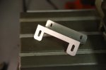
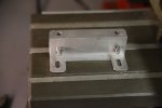
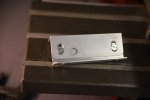
It did take a couple of tries to get a range of adjustment available in all the different elements of the Z shaped final mounting.
Having got this far with the mill assembled I couldn't put off taking the mill to bits any longer to drill the end of the Y axis table.
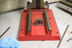
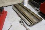
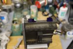
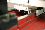
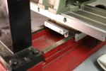
After that it was just a case of reassembling it.
So where were we?
The only possible mounting for the read head on the X axis is the end of the Y axis table. To do this I employed a couple more offcuts of aluminium angle these slightly deeper in section than that used on the Y axis reade head.
The brackets needed to fit around the Y axis lead screw so needed a bit of shaping.


It did take a couple of tries to get a range of adjustment available in all the different elements of the Z shaped final mounting.
Having got this far with the mill assembled I couldn't put off taking the mill to bits any longer to drill the end of the Y axis table.


After that it was just a case of reassembling it.
Rob Pulham
Western Thunderer
This seems to be the only shot that I have of the X axis scale in place with it's chip cover.
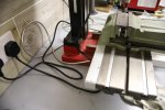
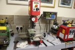
Then I mounted the display - you will note that the bottom Z Axis display is reading al zeros this is because at this point I was still awaiting the longer replacement scale.
There are quite a few options for mounting the display you can angle the bracket out from the side of the mill if you have somewhere to mount it. I chose to fix it to the bench alongside.
Then it was onto fitting the Z axis scale. This was reasonably straightforward in that I was able to fasten the scale itself directly to the rear of the column. I confess that I did initially get it slightly too low which reduced the amount that I could raise the head of the mill. Meaning that I had to redrill one of the holes higher up to get maximum height.
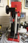
I was also able to finally use some of the brackets and mounting plates that came with the scales again fitting to the yoke which raises the head was reasonably straightforward.
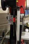
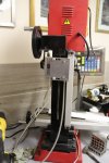
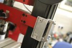
What did find was that I had to turn some spacers from aluminium bar to get the alignment between the read head and the yoke so that it ran up and down smoothly without rubbing on the chip cover.
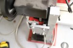
In conclusion, I am really happy with the DRO and now feel confident to do something similar on my lathe at some point. I do agree with Nick Baines comment that having that level of accuracy does tend to get you a little hung up on hitting 0.005 of a millimetre...


Then I mounted the display - you will note that the bottom Z Axis display is reading al zeros this is because at this point I was still awaiting the longer replacement scale.
There are quite a few options for mounting the display you can angle the bracket out from the side of the mill if you have somewhere to mount it. I chose to fix it to the bench alongside.
Then it was onto fitting the Z axis scale. This was reasonably straightforward in that I was able to fasten the scale itself directly to the rear of the column. I confess that I did initially get it slightly too low which reduced the amount that I could raise the head of the mill. Meaning that I had to redrill one of the holes higher up to get maximum height.

I was also able to finally use some of the brackets and mounting plates that came with the scales again fitting to the yoke which raises the head was reasonably straightforward.


What did find was that I had to turn some spacers from aluminium bar to get the alignment between the read head and the yoke so that it ran up and down smoothly without rubbing on the chip cover.

In conclusion, I am really happy with the DRO and now feel confident to do something similar on my lathe at some point. I do agree with Nick Baines comment that having that level of accuracy does tend to get you a little hung up on hitting 0.005 of a millimetre...
Overseer
Western Thunderer
Thanks for showing us how you fitted the DROs to the mill Rob. I have the same/similar mill and have been thinking of doing something similar. The local Seig importer (ausee.com.au) sell DRO parts which look good to me so will probably use them. I tend to use the fine control for the final Z axis adjustment and your fitting doesn’t seem measure the fine control Z axis movement. Would it be possible to mount the reading head to the motor housing or somewhere else to measure both the main and fine Z axis adjustments? Or have I not understood your mounting?This seems to be the only shot that I have of the X axis scale in place with it's chip cover.
View attachment 215794
View attachment 215795
Then I mounted the display - you will note that the bottom Z Axis display is reading al zeros this is because at this point I was still awaiting the longer replacement scale.
There are quite a few options for mounting the display you can angle the bracket out from the side of the mill if you have somewhere to mount it. I chose to fix it to the bench alongside.
Then it was onto fitting the Z axis scale. This was reasonably straightforward in that I was able to fasten the scale itself directly to the rear of the column. I confess that I did initially get it slightly too low which reduced the amount that I could raise the head of the mill. Meaning that I had to redrill one of the holes higher up to get maximum height.
View attachment 215796
I was also able to finally use some of the brackets and mounting plates that came with the scales again fitting to the yoke which raises the head was reasonably straightforward.
View attachment 215797
View attachment 215798
View attachment 215799
What did find was that I had to turn some spacers from aluminium bar to get the alignment between the read head and the yoke so that it ran up and down smoothly without rubbing on the chip cover.
View attachment 215800
In conclusion, I am really happy with the DRO and now feel confident to do something similar on my lathe at some point. I do agree with Nick Baines comment that having that level of accuracy does tend to get you a little hung up on hitting 0.005 of a millimetre...
Rob Pulham
Western Thunderer
Hi Frazer,
No, you haven't misunderstood the mounting, it doesn't measure the fine feed. I did wonder if this might be a problem but so far since fitting it I have found that I haven't needed to use the fine feed. I just use the Z axis on the column to set the height/depth and and then lock the head as I take each pass. You can also buy Fine feed DRO kits which are self contained with their own readout but so far I haven't explored them in any detail.
No, you haven't misunderstood the mounting, it doesn't measure the fine feed. I did wonder if this might be a problem but so far since fitting it I have found that I haven't needed to use the fine feed. I just use the Z axis on the column to set the height/depth and and then lock the head as I take each pass. You can also buy Fine feed DRO kits which are self contained with their own readout but so far I haven't explored them in any detail.
Peter Cook
New Member
Thanks for the information on the DRO fitting. As a question how much Y-axis movement did you loose? The fitting and covers look quite deep.
If you are interested in adding a simple DRO to the quill, this is what I did

Its a cheap (<£7 on Amazon or Ebay) tyre depth guage. The wings on the side were cut off and a couple of holes drilled to match the existing mounting holes for the (long discarded) chuck guard. A bit of plastic tubing ( actually the plunger from a plastic syringe) with a flat top that fitted over the metal pin with a small neodymium magnet glued to the end. I simply glued the pin into the plastic tube.
The magnet sticks to the bottom of the quill and pulls the slider back up as it rises.
OK it's basic and reads sideways, but it is infinitely superior to the markings on the fine feed wheel, and doesn't suffer from backlash. Oh and very cheap!
I bought a couple, and the second one makes an excellent depth guage for slots and holes after milling the end flat.
If you are interested in adding a simple DRO to the quill, this is what I did

Its a cheap (<£7 on Amazon or Ebay) tyre depth guage. The wings on the side were cut off and a couple of holes drilled to match the existing mounting holes for the (long discarded) chuck guard. A bit of plastic tubing ( actually the plunger from a plastic syringe) with a flat top that fitted over the metal pin with a small neodymium magnet glued to the end. I simply glued the pin into the plastic tube.
The magnet sticks to the bottom of the quill and pulls the slider back up as it rises.
OK it's basic and reads sideways, but it is infinitely superior to the markings on the fine feed wheel, and doesn't suffer from backlash. Oh and very cheap!
I bought a couple, and the second one makes an excellent depth guage for slots and holes after milling the end flat.
Rob Pulham
Western Thunderer
Hi Peter,
In real terms the scale and chip shield takes about 28mm off the Y travel and I could decrease that if I take the chip shield off should I ever need a little extra.
But as it is, the mill vice overhangs the table at the rear by about 26mm so unless I find that I need to work on something that I need to clamp directly to the table, it really makes only a couple of millimetres difference.
I like your idea for a quill DRO. It's nice and simple, something that I might replicate at some point as I too have those two mounting holes...
I had also considered getting a cheap vernier and modifying it in a similar way, to make a DRO for my lathe tailstock quill. Which is not only basic in measurement it's also in imperial so the smallest increments (1/16th"?) are almost 1.6mm
Peter Cook
New Member
A post to thank Rob for the inspiration, and a follow up to Overseer's question about mounting to the motor plate - which triggered the possibility.

I have now installed DROs to all three axes of my SX1LP. X and Y installation was almost identical to Robs implementation, although I got longer scales. 150mm for Y, 350mm for X and 250mm for Z, to use all the nominal travel of the axes. It makes the installation a little untidy as the scales overall are longer than the table. But they don't get in the way. I also accidentally ordered 1 micron scales. I still need chip guards and the cabling needs a tidy up.
Rather than build the bracket that Rob did for the X axis read head, I made a couple of aluminium spacers, threaded M5 outside to screw into the read head with 3mm through holes. M3 tapped holes in the end of the saddle allow the read head to clear the Y nut and leadscrew. The spacers were made thicker, and turned down to an appropriate thickness in the final fitting of the scale.

Overseer's query (post #26) made me look at the mill, and I found that the bottom plate of the head is fastened to the motor plate with M5 bolts. Replacing one with a longer bolt gave me a projecting M5 thread to which I could attach the Z axis read head using a sleeve nut.

To make it as rigid as possible I used some scrap 25mm square bar as the carrier and one of the brackets from the scale kit. This works well. It is a little less rigid than the X & Y, and leaning on the head moves the indication some 10-20 microns, but if I let go it goes back to the original reading within a couple of microns. It measures both quill and Z movement. First impressions are good.


I have now installed DROs to all three axes of my SX1LP. X and Y installation was almost identical to Robs implementation, although I got longer scales. 150mm for Y, 350mm for X and 250mm for Z, to use all the nominal travel of the axes. It makes the installation a little untidy as the scales overall are longer than the table. But they don't get in the way. I also accidentally ordered 1 micron scales. I still need chip guards and the cabling needs a tidy up.
Rather than build the bracket that Rob did for the X axis read head, I made a couple of aluminium spacers, threaded M5 outside to screw into the read head with 3mm through holes. M3 tapped holes in the end of the saddle allow the read head to clear the Y nut and leadscrew. The spacers were made thicker, and turned down to an appropriate thickness in the final fitting of the scale.

Overseer's query (post #26) made me look at the mill, and I found that the bottom plate of the head is fastened to the motor plate with M5 bolts. Replacing one with a longer bolt gave me a projecting M5 thread to which I could attach the Z axis read head using a sleeve nut.

To make it as rigid as possible I used some scrap 25mm square bar as the carrier and one of the brackets from the scale kit. This works well. It is a little less rigid than the X & Y, and leaning on the head moves the indication some 10-20 microns, but if I let go it goes back to the original reading within a couple of microns. It measures both quill and Z movement. First impressions are good.

