Chas Levin
Western Thunderer
Hello all, this workbench thread will cover my various modelling activites - mainly, but by no means exclusively GNR and LNER.
Like a lot of people, I left the RTR railway and the mainly military Airfix kits of my youth and didn't return to modelling for about 30 years, by which time a renewed interest in railways and a very different railway kit industry suggested building railway vehicles, something that hadn't occurred to me before.
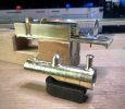
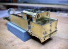
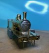
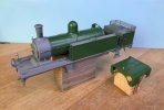
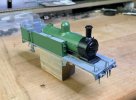
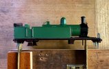
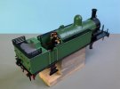
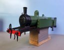
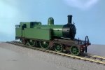
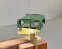
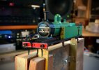
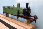
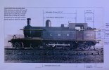
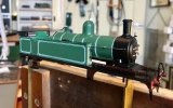
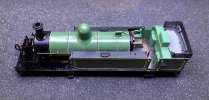
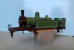
I posted a photo of part of my current project - the loco body of a 4mm OO gauge London Road Models GNR C2 (later the LNER C12) - in my first post in the New Members section and a couple of replies mentioned that people are very keen on lots of photos here: I hope they meant it!
I thought I'd start with a potted history of this current build; I always take a lot of photos as I work (I find them very useful later on in the build and if and when I build something similar later on, not to mention if an older model needs dismantling) so I've no shortage of material. I've tried to keep to a minimum for routine parts of the process, with a few more photos - and some explanation where necessary - for things that may not be quite so obvious.
So, here goes - the first few should be self-explanatory:
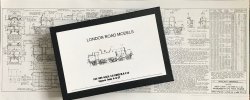
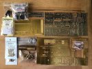
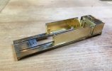
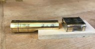
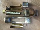
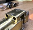
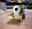
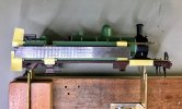
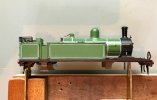
This was my first etched loco and only my second loco build of any type (the first was a DJH WM J9 on a rigid chassis) and I wanted to try out some form of compensation, so I took the superstructure up to the collection of pre-fabricated sections you see in the last photo, before breaking off to learn about compensation, eventually deciding to try a Flexichas-style compensation beam as my first attempt.
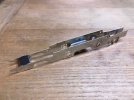
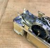
You can just see in the above picture of the frames that they taper in quite a bit at the back; this was a slight modification of the kit to accommodate the rather tight curves on my layout and I also deviated from the LRM instructions by incorporating LRM's Radial Truck etch - usually supplied with some of their LNWR kits but also available separately. Happily for me, it is actually prototypical for the particular C2 I'm modelling!
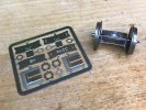
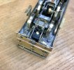
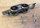
The truck fits into the same cut-outs in the frames that you'd use for hornblocks and below you can see the central lateral guide spring (that goes through a little eye in the top of the truck) and the two vertical tracking springs that keep the truck where it needs to be.
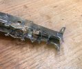
The hornblocks - which are on the front drivers, the compensation beam running between them and the front bogie - are MJT and I mounted the cosmetic etched springs for that axle on removable pieces of 1mm x 1mm brass angle secured by 14BA bolts, so the axle can be dropped out if needed:
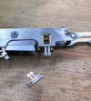
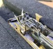
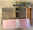
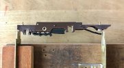
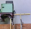
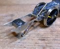
The compensation beam took a little thought, as to how it would have the desired weight distribution effect on the bogie, whilst still allowing free lateral movement - the usual problems of course, but all new to me. I used a piece of U-section brass with a hole in, bound to the slightly angled end of the beam with tinnned copper wire before everything was soldered and cleaned up, as a combined weight transmitter and rubbing plate. The bogie's securing guide bolt comes down from the chassis above, going through both the bogie stretcher and the rubbing plate - hopefully the picture below makes it clearer:
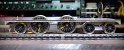
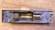
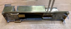
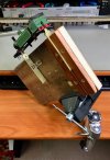
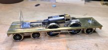
Everything came together quite nicely at this point and the chassis ran well, using a Mashima 1024 in a High Level Kits RoadRunner+ gearbox; LRM supply a one-stage Romford fold-up but because I wanted to drive the rear axle without intruding into the cab, I needed to fit the drive unit inside the firebox and boiler but partly underneath the cab floor, where the RR+ drive stretcher was an excellent solution. Plus, to be honest, I wanted to try making my own gearbox:
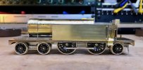
Right, I think that'll do for a first installment. I read the post about preferred photo size and I've resized everything so it should be within the requested limits - please let me know if not, as I did leave one or two a little larger where detail is relevant.
More to follow...
Like a lot of people, I left the RTR railway and the mainly military Airfix kits of my youth and didn't return to modelling for about 30 years, by which time a renewed interest in railways and a very different railway kit industry suggested building railway vehicles, something that hadn't occurred to me before.
I posted a photo of part of my current project - the loco body of a 4mm OO gauge London Road Models GNR C2 (later the LNER C12) - in my first post in the New Members section and a couple of replies mentioned that people are very keen on lots of photos here: I hope they meant it!
I thought I'd start with a potted history of this current build; I always take a lot of photos as I work (I find them very useful later on in the build and if and when I build something similar later on, not to mention if an older model needs dismantling) so I've no shortage of material. I've tried to keep to a minimum for routine parts of the process, with a few more photos - and some explanation where necessary - for things that may not be quite so obvious.
So, here goes - the first few should be self-explanatory:


This was my first etched loco and only my second loco build of any type (the first was a DJH WM J9 on a rigid chassis) and I wanted to try out some form of compensation, so I took the superstructure up to the collection of pre-fabricated sections you see in the last photo, before breaking off to learn about compensation, eventually deciding to try a Flexichas-style compensation beam as my first attempt.

You can just see in the above picture of the frames that they taper in quite a bit at the back; this was a slight modification of the kit to accommodate the rather tight curves on my layout and I also deviated from the LRM instructions by incorporating LRM's Radial Truck etch - usually supplied with some of their LNWR kits but also available separately. Happily for me, it is actually prototypical for the particular C2 I'm modelling!

The truck fits into the same cut-outs in the frames that you'd use for hornblocks and below you can see the central lateral guide spring (that goes through a little eye in the top of the truck) and the two vertical tracking springs that keep the truck where it needs to be.

The hornblocks - which are on the front drivers, the compensation beam running between them and the front bogie - are MJT and I mounted the cosmetic etched springs for that axle on removable pieces of 1mm x 1mm brass angle secured by 14BA bolts, so the axle can be dropped out if needed:

The compensation beam took a little thought, as to how it would have the desired weight distribution effect on the bogie, whilst still allowing free lateral movement - the usual problems of course, but all new to me. I used a piece of U-section brass with a hole in, bound to the slightly angled end of the beam with tinnned copper wire before everything was soldered and cleaned up, as a combined weight transmitter and rubbing plate. The bogie's securing guide bolt comes down from the chassis above, going through both the bogie stretcher and the rubbing plate - hopefully the picture below makes it clearer:


Everything came together quite nicely at this point and the chassis ran well, using a Mashima 1024 in a High Level Kits RoadRunner+ gearbox; LRM supply a one-stage Romford fold-up but because I wanted to drive the rear axle without intruding into the cab, I needed to fit the drive unit inside the firebox and boiler but partly underneath the cab floor, where the RR+ drive stretcher was an excellent solution. Plus, to be honest, I wanted to try making my own gearbox:


Right, I think that'll do for a first installment. I read the post about preferred photo size and I've resized everything so it should be within the requested limits - please let me know if not, as I did leave one or two a little larger where detail is relevant.
More to follow...


