7mm Another attempt

Roger Pound

Western Thunderer
.........perhaps this is the reason I haven’t had any problem the cork might give a little.
David.
I have used cork on ply for years and would definitely confirm cork does have movement - not a lot but apparently enough to alleviate some of the problems discussed here. I may be talking out of turn as I have been out of 0 gauge for a year or two and now use ready-made track in 00 and H0e. Despite that wide range of temperature experienced by my layouts, both in my garage and shed, I have been lucky enough to avoid problems of this nature. The rates of expansion and contraction of nickel silver rail will remain constant in any location, relatively any way, at least so I would assume -:confused: - thus I would venture a decent foundation is definitely the answer.

Start with the baseboard Julian and I am sure that with persistence and the track materials with which you are obviously at home, you will prevail. :)

Roger :thumbs:
 

Jordan

Mid-Western Thunderer
Well after a fair time I managed to get "upstairs" this afternoon to look at the layout......wish I hadn't!!! I know I have used copper clad sleepers and soldered rail but it is only code 100....the siding has completely lifted and split the sleepers.
Very disheartened.,.
Julian View attachment 188430
It would be easy to be flippant & say the answer is to lay it like that in the first place...
20220717_161439.jpg

BUT...... there are differences. I note in your photo the bare blockwork wall behind the layout - is the loft (I'm assuming?) properly boarded & insulated including under the roof? If not I dread to think what temperature it can reach in there without insulation. I have a Velux window but keep the blind down so that none of the layout is subject to direct sunlight, which can raise the temperature substantially in a small area.
My boards are Knauf Spaceboard extruded styrofoam. There is a bit of expansion in hot weather as currently I have slight gaps between each fascia strip, but the track isn't affected (as far as I can tell, anyway!!)
Finally only my switches (turnouts/points) use a 'skeleton' of a few pcb ties (sleepers) - all the rest are wooden ex-coffee stirrers or balsa strip with the rails spiked down with Peco track pins. These go right through the glue holding the ties & in some areas a sub-road bed of balsa or hardboard strip, and into the foam. The sheer amount of pins & the depth they go seems to make a big difference to rail security. I also left a 1mm gap at each rail join to allow for expansion.
I'm surprised to see the amount of distortion on your track, though, especially as it's a short length.
 

Stephen Freeman

Western Thunderer
I can undrstand why the loft is not insulated given the location but it might be prudent to insulate the roof to try and keep it a bit cooler at this time of year. As for using copperclad and ns rail, it would be even worse if you used plastic based track. In actual fact I have always found that direct sunlight is the worst for expansion even when the ambient temperature is not excessive.

What I did find was that copperclad track in 00 outside ballasted with the usual granite chippings secured by plenty of varnish was fairly inpervious to anyything the British weather could throw at it.
 

Joe's Garage

Western Thunderer
Yes Jordan you are right the loft is not insulated so the temperature range is vast. Guess I can call this a massive learning experience.
I have been reconsidering the construction and will utilize another board which I have varnished in the past, no warping yet.
It is a good time to reconsider the track too, although the points seem fine, they are skeleton construction as far as the copper clad sleepers are concerned.
Watch this space...
Julian
 

ovener

Western Thunderer
Julian, that must be very disheartening to see your carefully laid track like that; my commiserations to you.
I cleverly used a couple of pieces of scrap shipping plywood for my first railway 2mm lockdown project which was not the best idea as it is uneven, has quite a few holes in the layers, splinters and delaminates quite easily. Luckily I used stick down foam as the track base which I think has smoothed out a lot of the bumps and tiny track screws to adjust the height if needed.
I have certainly learnt a lot in a short time...
Scant consolation to know that the Big Railway has the same problem.
Richard
World's worst railway track
 

simond

Western Thunderer
If you search YouTube, there are some scary videos, I recal one where the engineer is heard to exclaim something, as he spots an expansion-induced dogleg in the track about a quarter of his braking distance away, and then you just wait…

expansion & contraction is going to happen - if you fix the ends, the middle will have to go somewhere, and the forces involved are very considerable. Plastic base track can allow the rails to slide along, soldered copperclad will not, if the sleepers are fixed down, eg with pins or screws. I’d suggest making your pointwork with copperclad, you can do panels of track too, as these will expand and contract together, and so will not deform, as long as they can move. So glue them with something flexible, eg copydex, even evostik.

how much will it move?


nickel alloys 10-15, copper alloys 15-20, microns per metre per degree C

so if you lay your track when it’s actually zero degrees, literally freezing, and your loft gets up to 30C, which is pretty hot (but not garden-baseboard-in-direct-sun-hot, you could double it for that) you might need to put in an expansion gap of 15 x 30 = 450 microns, per metre of track. That’s 0.45mm. I’d be slightly more generous In this case.

curves help too, as a very small sideways move will accept much of the expansion.

hth
Simon
 

Joe's Garage

Western Thunderer
I would not have liked to drive that loco on that track!!!!
Yes Simon I agree with the expansion and remember the calculations back in Motor Vehicle Science.
I think I can conclusively say it is the combination of baseboards that have warped and the track expanding, in effect doubling the problem.
So in a quiet moment this morning I drew out some ideas. I am going to use a baseboard which I have had for many years but have treated it to varnish etc so it shows no sign of warpage.
As I said in beginning I wanted short boards to aid movement and storage. So I will look at the station area/siding first.
Only thing is I may use some Flexi track to enable some movement of the rail.
Thank you gentlemen for the feedback, I'll get on with the model .... hopefully!!
Cheers
Julian
 
Yes Jordan the chassis is the Lima Plymouth switcher, runs very well it very noisy. Will seek out some plastic grease on my return.
I originally built the tram with an old Triang Jinny chassis with the original wheels fitted on silver steel axles and turned spacers to 32 mm gauge. Ran very well until the old motor bit the dust, the Lima switcher provided a cheaper fix that a replace motor. I built this loco way back in the 90s and would not part with it so it is bit like the Colonel Stephens philosophy, keep running on a shoestring!

Hi Brian, yes they are very nice locos, I built the 2021 as a possible Dorset engine, West Bay? There is also a lovely picture of a saddle tank 060 having run through the buffers at Aberayron before WW1 so maybe the scenario for this little layout may be the proposed not built branch to New Quay.

I have one wagon at the moment but will have to get a few more, preferably pre-grouping. Photos of the above welsh terminus show so many pre-grouping company wagons including North British in its early days.

Thanks for the likes

Julian
Hello Joe
Was wondering if you can remember what the 2021 0-6-0st was like to build as I am thinking of possibly getting a Zero Zephyr kit as Ian Young at CSP Models has reintroduced the range with a few upgrades to them?.
 

Joe's Garage

Western Thunderer
Hi Paul
I have built 2 now, the first one being Eric Underhill's original kit and then a later ABS Zero Zephyr kit.
The main difference was the earlier kit had a resin footplate and the build was describe in an early MRJ. The later had more etched brass, footplate, cab etc.
I found both quite straightforward and both were built rigid with no problems. The earlier resin based model being lighter need weight in boiler but with the cab and footplate in brass I didn't put weight in.
Both ran/run very well, even on my little layout.
I would be interested in what the upgrades are now?
My recommendation is a definite yes if you are okay with etched brass, in fact it is quite a good introduction as I presume the saddle tank is still a resin casting?
Enjoy
Julian
 

Joe's Garage

Western Thunderer
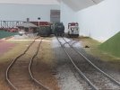
Well it's been a while, which is good in a sense as my immediate reaction was to "tip" the lot and wait until the pending house move was completed and I had somewhere to call a railway home!
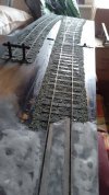
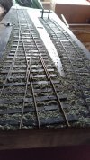
When I was emptying the loft and bringing the boards down I noticed the track had settled back to something resembling "normal" so as I was tasked to get the layout ready to move I made the excuse that I needed to ballast and resecure the track on the damaged board...here are some hasty shots of the rough ballasted track.

IMG_20230817_125528.jpg
IMG_20230817_125444.jpg

The boards are safely stored and away from drastic temperature variations until the move.

The progress on the station building is still at the "flat pack" stage due to storage but once unpacked will resume assembly.

The moral of the story...do not listen to ERIC in times like this.... Emotional Reaction Impedes Control....I could have scraped the little layout. I know it easy to say but I had a chance to consider the decision.

Julian
 

David Hall

Western Thunderer
Well it's been a while, which is good in a sense as my immediate reaction was to "tip" the lot and wait until the pending house move was completed and I had somewhere to call a railway home!
When I was emptying the loft and bringing the boards down I noticed the track had settled back to something resembling "normal" so as I was tasked to get the layout ready to move I made the excuse that I needed to ballast and resecure the track on the damaged board...here are some hasty shots of the rough ballasted track.

View attachment 194487
View attachment 194488

The boards are safely stored and away from drastic temperature variations until the move.

The progress on the station building is still at the "flat pack" stage due to storage but once unpacked will resume assembly.

The moral of the story...do not listen to ERIC in times like this.... Emotional Reaction Impedes Control....I could have scraped the little layout. I know it easy to say but I had a chance to consider the decision.

Julian

Hi Julian.

I'm really pleased you didn't fall prey to ERIC! I look forward to seeing some progress in due course, amongst all the busyness on life.

Dave
 

Joe's Garage

Western Thunderer
Has it really been 15 months since I made any progress on this little layout but earlier last week I managed to "find" some time to escape the trials and tribulations of this hectic world and make a little input to my "flatpack" shed.
The lovely thing about card modelling is that if you make a mistake it won't break the bank to redo.
It may only have been an hour or two but it certainly made me feel better and I was quite impressed at the size of the small shed. (Just to remind readers it is based on the WC&PR West Wick station).
I have attached some photos showing the basic assembly. Funny at the same time our next door neighbour was having a wooden garage erected!!

I enjoyed the time away and being immersed in our little world....very good for our souls.

"For me, one of the real pleasures of historical modelling is using that special combination of model and imagination to allow me to become immersed in another time and place - the distractions of the contemporary world are momentarily filtered away and the sights, sounds, smells and sensations of the model world take their place."
Stephen Williams, Faringdon. Model Railway Journal No. 77 1995.

IMG_20241218_143814.jpg
IMG_20241218_143832.jpg
IMG_20241219_144037.jpg
IMG_20241219_144110.jpg

I remember Simon (of Bath) saying to me....

Best thing to do is to have a go, what have you got to lose?

Then show us how it went or not, you would really enjoy it even more than talking about it, honestly…..

Thank you Simon for the motivation I will never forget these words.
 

Joe's Garage

Western Thunderer
Well a bit more progress, well the roof is being formed from similar card. The original had a corrugated sheet roof but I will add roof material to this simple base to give it strength.

IMG_20250103_192944.jpg

The engine plate is quite a nice weight and is merely holding down the roof to get the overhang right in regards to the photos available on the WC&PR website.

IMG_20250103_193053.jpg

The brass engine plate is an interesting item from my late Father who was researching the life of Peter Willans, who designed a vertical triple expansion steam engine.

IMG_20250103_193004.jpg
 

Joe's Garage

Western Thunderer
A question please my friends, I have been rummaging in my boxes and found a bag of various plastic card sheets, strips etc. Amongst these were a couple of corrugated sheets which look fairly acceptable to represent a typical roof for the station building.
My question is, and I apologise for the poor quality of the photos should I cut the individual widths of sheeting or lay just one sheet across the roof. In my mind the overlap is not really visible so me thinks I will have to do some weathering to bring this out. What do others think? The edge of the old sheets are dulled due to age, so you can see the difference but when painted it will not be so noticeable.
Also does anyone know what size these would have been, the sheets I mean as I already know the pitch.
Amazing what you find in the boxes......
Thank you
Julian

IMG_20250130_143504.jpg IMG_20250130_143303.jpg
 

Allen M

Western Thunderer
Also does anyone know what size these would have been, the sheets I mean as I already know the pitch.
Hi Joe
As I remember it. When I worked in the local steel mills in the 1950s to mid 60s the building was a frame covered in corrugated sheet. They where 2ft 3in wide and laid at 2ft spacing giving a 3in i.e. 1 corrugation overlap. The lengths where generally 6ft or 8ft. The overlap for the vertical varied from about 3in to 1 ft . I think for ease and saving a bit of cutting. However the overlap line on the outside of the building was normally straight unless there was openings to get round.
In the dry areas they seamed to last for years but in the acid pickling areas it seamed kike a near full time task keeping the rain out.
Note not guaranteed correct but I think should be OK.

Regards
Allen
 

James Spooner

Western Thunderer
A question please my friends, I have been rummaging in my boxes and found a bag of various plastic card sheets, strips etc. Amongst these were a couple of corrugated sheets which look fairly acceptable to represent a typical roof for the station building.
My question is, and I apologise for the poor quality of the photos should I cut the individual widths of sheeting or lay just one sheet across the roof. In my mind the overlap is not really visible so me thinks I will have to do some weathering to bring this out. What do others think? The edge of the old sheets are dulled due to age, so you can see the difference but when painted it will not be so noticeable.
Also does anyone know what size these would have been, the sheets I mean as I already know the pitch.
Amazing what you find in the boxes......
Thank you
Julian

View attachment 232551 View attachment 232550
Hi Julian,

I guess it depends on whether you are trying to replicated corrugated iron or asbestos (which was a tad thicker). Either way though, the thickness of the material, scaled down by 43 times, means that it would be almost impossible to replicate unless you used some very thin foil. Given our life expectancies, I would go with the full sheet on the roof and dirty it with paint…

Nigel
 

Osgood

Western Thunderer
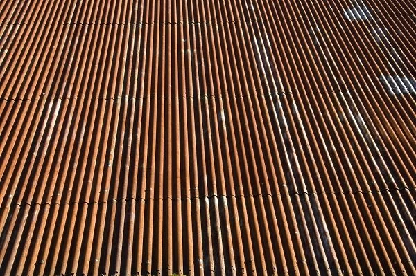
A quick image search for corrugated iron roof yielded this:

Roofs rust in time but stay good for a while so determining age you wish to show it at and stage of decrepitation might influence how obvious the sheets joints might be.
Typically the vertical joints are almost completely invisible whilst horizontal joints are more noticeable.
Individual sheets weather differently and so the vertical joints can become more defined by virtue of different colours.

Maybe scribing would help, both visually and as an easy way of crisply separating different weathering colours?
Vertical easy to do (2/3 down a side), horizontal more challenging.
I just found a roll of 1970s vintage brass 4mm corrugated sheet material (Ambiss?) approx 8ft wide (scale….) and aim to scribe the verticals. I think the horizontal overlapping joints might be too pronounced but won’t know until I have a go.

I’m looking for a 7mm equivalent.
There is a thread on here somewhere discussing a rolling mill - neat piece of engineering if you can get the pitch right!
 
Last edited:

Pencarrow

Western Thunderer
I agree. Despite the fact that the thickness of sheet overlap in real life is tiny when modelled to scale, I would still not use an entire sheet. I have been cutting the sheets into panels for some years now.

For the horizontal joints between rows I do not overlap the sheets though. Instead I pack underneath the lower edge of the upper sheet with something like 5 to 10thou material. This is just enough for the eye to pick up the line but not too much to look silly.

For the vertical joints between sheets I just butt them up, with a tiny tiny gap between sheets. Again this seems to be enough to give the eye what it expects to see. You could pack under one vertical edge to give more of an impression of overlap, but this doesn't seem as necessary for the overall effect as the horizontal joints.

IMO a flat sheet used in one hit will always look like a single flat sheet unless the builder is extremely useful with a paintbrush. Even then light across the roof will not pick up any joints.

This is a card and MDF kit. I deviated from the instructions...

The roof corrugated panels were included as a single sheet of card per roof but with perforations mimicking joints.
PXL_20240714_144705167.jpg

I cut the sheet into rows and then I cut narrow strips of paper and fixed to the lower edge of each row.
PXL_20240714_145546201.jpg

Each row added on turn.
PXL_20240714_145708704.jpg

PXL_20240714_145821680.jpg

PXL_20240714_145951428.jpg

Horizontal joints do just stand proud.
PXL_20240714_153929512.jpg

Better after painting.
PXL_20240818_170601041.MP.jpg
 
Last edited:
Top