A 3D Printing Experience

Dog Star

Western Thunderer
Thank you Mick (@mickoo), an informative answer which, in addition to explaining why FEP tension is important, has answered another question about peel forces.

Thank you Simon (@simond) for the Wiki link. Interesting to learn, almost fifty years after graduating in Organic Chemistry, that FEP is a thermo-plastic (softens / hardens with changes in temperature) whilst PTFE is a thermo-setting / hardening plastic which becomes and remains hard after the application of heat.

regards, Graham
 

Boyblunder

Western Thunderer
Has anyone in the forum tried using some sort of PTFE spray on FEP film to aid release? So far I haven't had the problem with the Anycubic Mono 4K but got through loads of FEP films on the Elegoo Saturn, no doubt mainly through my own ineptitude. There is conflicting advice on the 3D printing forums, some say dry PTFE spray works, others think it is liable to get on the build plate and make detachment failures worse.
 

Mike Trice

Western Thunderer
I'm guessing the Phrozen uses a securing ring around the base of the vat that pulls in the FEP as you tighten the screws?

Pretty much like Epax and you don't really get much choice in the tension setting, it is what it is. So long as it remains constant then tension isn't as critical as it can be, all one needs do is adjust exposure times to get the best results.
With the Photons, Anycubic recommend using a spacer to set the initial "slack" in the FEP which is then tensioned as you suggest. Insufficient slack to start with could cause the FEP to be overtensioned when tightening the screws. Also FEP stretches over time so may not maintain its tightness. I use a 13mm bottle cap to tension mine (I actually printed a 13mm cap rather than use one off a bottle) however I have used and seen people tuning their FEP to a specific frequency range.

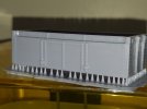
For people trying to work out what on earth I am talking about the FEP (fluorinated ethylene propylene) is a transparent sheet that is stretched across the resin VAT allowing the UV light to pass through it and set the resin. Being stretched it reacts like a drum when tapped with the fingers and this frequency can be detected and tuned using a tuning app on a mobile phone.
 

Mike Trice

Western Thunderer
Sorry it was on my wife's phone and she has changed phones since. Will see if I can find something.

Spectroid for Android.
 

Rob R

Western Thunderer
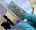
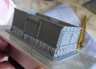
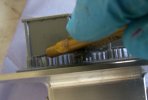
Latest effort - progress of a sort.

Upside down, flat, large supports, 25um layer (and a new FEP).
Still wet from washing.

The centre section of the solebars has curled inwards and the headstocks outwards so we are back to a change in surface area on the FEP causing issues.(Sides 1mm thick, solebars/headstocks 2mm).
Need to put in heavy supports/bracing at just below floor level, or another scarificial lump (hollow box) within the footprint to balance out the extra surface area of the underframe?
Any surface blemishes will all be out of sight there and can be filed flat after curing.
Success.jpg
 

JimG

Western Thunderer
After a month and a half I'm back with the top door version of the mineral. The time wasn't all spent on the wagon since I knocked out a couple of sets of etch artwork for two of the S Scale Society members but I did spend a lot of time getting my head around the Assembly functions of Solid Edge. Doing the non-top door version of the body had only required the simplest assembly operations and I got on quite well with them first time round. But with the top door I had to use more complex operations and there I hit a brick wall - with repeated error messages when trying to assemble parts. I spent hours ploughing through the SE documents but with very little luck. The internet and Youtube also were not much help. Finally the penny dropped and I got the assembly done. The problem was that I had to place parts parallel to other parts and I was trying to use the "Parallel" option in Assembling which wasn't working. I finally tried using "Planar Align" with a floating offset, and it all worked. :) I still haven't found out what the "Parallel" function actually does. :)
:
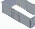
Adding the top doors to the existing non-top door body was pretty straightforward. I set up a plane with a sketch the size of the top door then cut out the top door apertures using that sketch.

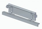
The top door was built up from its parts as a separate sub assembly :-

16TMineral-036.jpg
I found that access to the prototype working drawings which AndyB got me a few years ago was a great help in doing this work. I only had to apply some slight modifications to accommodate the compromises that I had included in the body - like the top tubular edge has been increased to 1mm diameter to better match the overwide top angle edge of the body side, that in turn being required because of the necessarily over-thick body sides.

16TMineral-035.jpg

And here's the top door inserted in the side.

I'm now producing good prints - still orientated right way up with loads of light supports to keep the top edges in line.

16TMineral-037.jpg

16TMineral-038.jpg

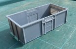
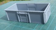
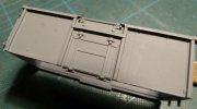
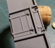
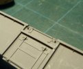
Here's a couple of pictures of the latest print with a light scoosh of Halford's Grey Primer and the benefit of the lunchtime sun. I hadn't cleaned the support pips off and they didn't look too obvious to the eye, but sure as fate, the camera homes in on them. :)

Later...

16TMineral-039.jpg

16TMineral-040.jpg

I got a conscience about the support pips so I had a go at them with the craft knife and I needed my Optivisor to see them. :) I can still see some in the pictures which I couldn't see in my hand under the work light. :)

If members of the S Scale Society want some prints they will be provided straight off the printer so that it's their responsibility to clean up the pips. :)

Jim.
 

Simon

Flying Squad
That really looks very good Jim, well done and lucky S scalers to have it made available to them.

Simon
 

Boyblunder

Western Thunderer
That looks excellent to me. I'm struggling with anything large, could you possibly put up a photo of the body with your support system still in place please? (so I can shamelessly copy it of course).
Robin
 

michael080

Western Thunderer
Looks great!

but ... you won't be able to pull the securing wedges at the top doors until you cut back the top angle profile a little bit.

16TMineral-040_cr.jpg

Michael
 

JimG

Western Thunderer
That looks excellent to me. I'm struggling with anything large, could you possibly put up a photo of the body with your support system still in place please? (so I can shamelessly copy it of course).
Robin
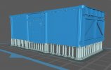
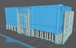
Robin,

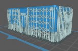
The body is placed full square, right way up in the slicer and then medium weight supports are placed all round the underside of the body.

16TMineral-041.jpg

The body sits up by 6mm from the base. The bottoms of the stanchions are also supported. The medium supports have a 0.4mm ball end with 0.2mm contact depth. All these supports are on the underside so any pips left can easily be cleaned off by rubbing the whole body on a piece of sandpaper on a glass sheet.

The next thing is to support details on the doors - end and side - which are overhangs with the body sitting square on its base.

16TMineral-042.jpg

I actually avoided having to do any supporting of the hinges on the top door by drawing them to avoid overhangs which I managed to do without compromising the part.

Then all the top lips of the sides have to be supported.

16TMineral-043.jpg


The details and the top lips are supported by light supports with a dome end of 0.2mm diameter and a contact depth of 0.15mm. I find this to be the smallest diameter I can put on a support with the resin I am using. Also the end of the support is a cone with a dome end, not a cone with a reduced neck with a ball on the end since that reduced neck would be too narrow and would fail to print in my setup.

Also most of the supports have angled tops so that the main vertical support body is well away from the sides. I have found that if I get the vertical parts of supports too near body sides then I can get marking of the sides with the interaction between them during the printing process.

The whole thing would be easier if I could have orientated the body about 40 - 45 degrees where the amount of supports for details and lips would have been reduced almost to nil. But I could never get the sides to print properly at an angle. Mick Davies discusses this more fully earlier in this thread.

Also note that my sides taper from 1.2mm thick at the bottom to 0.6mm thick at the top. This was arrived at after a lot of trial and error, starting with 0.4mm thick sides all the way up and increasing thickness and intrucing a taper until things improved. :)

Jim.
 

Dog Star

Western Thunderer
I actually avoided having to do any supporting of the hinges on the top door by drawing them to avoid overhangs which I managed to do without compromising the part.
How did you draw the model hinges to provide a realistic representation of the prototype?
 

Boyblunder

Western Thunderer
Thanks for the comprehensive reply Jim, I will have a go next week. I've got Covid this week and after an easy start the last 2 days have been written off in bed. Thankfully feeling more lively today . Robin
 

paratom

Western Thunderer
I have been 3D printing items for clients for a number of years now and have come to the conclusion that the 45 degree rule when placing the item on the print bed is not always the best solution. If the wagon you are printing does not need to be seen inside then print the sides and ends flat on the build plate with no supports. This will save you a lot of time and will produce a better print. Doing it this way will also mean you can reduce the layer thickness speeding up your print time. For example if you were to print a cube printing it with a 10 micron layer thickness it would not look any better than had you printed it with a 60 micron layer thickness. On the other hand if you were printing a dome you would see the difference in print quality. If you want to print your wagon as a whole body why not print the bottom of the wagon flat on the print bed providing the bottom is flat and there are no recesses. One of the problems with supports is the removal of them from the model which can take a long time and damage the model if your not careful. I also cure my models while they are still on the build plate when using a washable resin. This insures that no warping of the model takes place when curing. Removal can be more tricky when you do this but this can be made easier if you have a flexible removable plate or in my case I use a razor blade that I slide under the item to release it from the plate.
 

JimG

Western Thunderer
Thanks for the comprehensive reply Jim, I will have a go next week. I've got Covid this week and after an easy start the last 2 days have been written off in bed. Thankfully feeling more lively today . Robin

Good that you are on the mend and thankfully not lasting too long. In my case three weeks in hospital on CPAP and Dexamethasone then five weeks at home on an oxygen machine. But I'm fine now with many thanks to the people who set up the clinical trials of suitable drugs to treat COVID very early in the pandemic, and the hospital staff who treated me.

I also took some pictures of how I deal with the print at the end.

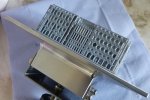
Here's the print off the machine still on the baseplate. It has been hung and drained on the printer to get rid of excess resin - that support lattice work can hold a lot.

16TMineral-044.jpg


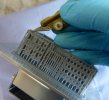
I keep the print on the baseplate and start removing the supports - the light ones around the top using a craft knife

16TMineral-045.jpg


I then pull the light supports off the print being slightly brutal and breaking them off at their bases.

16TMineral-046.jpg

...and I finally finished up with the body only supported on the medium supports around the bottom.

16TMineral-047.jpg

I then got the craft knife out again and cut the medium supports...

16TMineral-048.jpg

At this point I gave up on the pictures since I was having to shoot them using my left hand with the camera upside down so that I could get at the shutter. It was a real palaver. :)

The body was then cleaned in the ultrasonic cleaner and cured in my UV light box.

The print is quite soft and pliant when doing all the support stripping - the reason that I kept it on the build plate as the best way of holding it and avoiding damages. But it does retain its shape through the cleaning and curing. The brass floor when inserted will help to keep it that way.

I would probably have printed it directly on the baseplate as @paratom has suggested. I've used this method on several other prints with complete success, taking care to take some measures to limit "Elephant's Foot". But the end stantions on the mineral project below the body sides, so that put an end to the possibility.

Jim.
 
Top