You are using an out of date browser. It may not display this or other websites correctly.
You should upgrade or use an alternative browser.
You should upgrade or use an alternative browser.
Transport Age (Scorpio) 7mm BR Standard 3MT tank
- Thread starter P A D
- Start date
P A D
Western Thunderer
To my eyes Ozzy's drawing looks to be the Class 3. The step up in the front footplate is far higher than on the Class 2, the taper on the boiler too steep and the shape of the tank top edge is different.
Dave.
Hi Dave,
You are correct, it's the class 3. I should have put my stronger glasses on.

My apologies Ozzy.
P A D
Western Thunderer
Hello Peter,
now don't let that happen again.
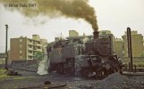
I've been going through photos on my other computer and came across this photo, it's a 9F 92214.
ATB
OzzyO.
I am duly chastised Ozzy!
Great image. It's an area of locomotives that can be very difficult to find period images of and one can only hope to find an image such as this taken in preservation.
Peter, Hello. Looking at the rods, I feel they'd be improved by "beefing up".
I've had look at the big ends on the connecting rods and it would easy enough to add the missing boss overlays. However, if I do that then I will have to thin the spacer between the rods, which will leave the connecting rod out of line with the crosshead and the coupling and connecting rods no longer parallel. If I leave the spacer as is to keep the rods parallel, I would need a longer Slaters' crankpin bush, as currently two bushes are just the right length for the width over the inner face of the coupling rod and outer face of the connecting rod. I'm thinking that when the return crank is on it won't be that noticeable so I may leave it as is, but I'm still prevaricating over it.
In the meantime I've been working on the slide bar/motion bracket, valve guides and valve gear. These are the bracket castings as they come.
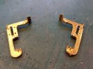
I'm removing those plates at the top as they don't fit up against the bottom edge of the tanks as they should. When I've got everything fitted and lined up I'll replace them with suitable brass strip filed to shape.
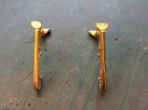
The trunnions are not the best of castings but should be OK after fettling up.
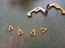
Here they are soldered to the brackets. The holes in the outer trunnions are tapped 10 BA so that can fit and remove the expansion link and radius rod when setting up the valve gear.
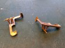
Here are the assembled radius rods and expansion links. As usual, I will set the rod in forward gear and a lolly stick is being used to prevent the link being crushed during drilling.
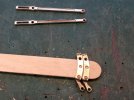
And screwed together.
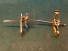
The holes in the anchor link at the drop link end are way too large and I've had to sleeve them with suitable tube turned down on the lathe. I soldered the tube through both holes then sawed through the gap and then outer ends and cleaned up. The hole at the other end will be OK as it matches the hole in the combination lever.
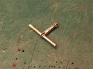
I've not heard back from Scorpio re the missing drop link and I suspect they may not be able to provide one. Therefore I set about making one from waste fret.
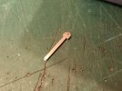
After making the first basic shape I soldered it to another strip of fret and cut/filed around it to make another. That's the kit one above.
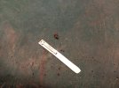
Here they are ready to fit to the crossheads. The assembled and sleeved anchor link is below with the parts for the other above. The holes are 1.3mm and the other parts will be joined using 1.3mm NS rod.
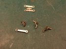
The valve guide castings are also quite crude, but I've got them drilled out and the valve rods slide nicely. I've tried to improve the appearance by wrapping an overlay of thin brass around the valve chest on the one on the left, but it needs more work and the one on the right is as it comes.
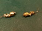
I was able to adjust the angle of ghd cylinders and slide bars to gain a little more clearance between the connecting rod and the lower bar.
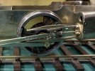
Cheers,
Peter
Paul Tomlinson
Western Thunderer
Peter, you're putting in a lot of work to achieve what will be a fine finished model, and I think it's worthwhile adding a ha'porth of tar on the rods. My "82045" link shows the part-machined coupling rod and the transition to the boss, which is a treat for my eyes. Re. the connecting rod - I confess I'm a fan of Premier milled rods, and Billy does list one for this loco. In MRJ (299) Barry Norman substituted Premier rods on his Connoisseur J15, and describes the improvements he made to them. But some esteemed modellers favour etched rods, and who am I to argue? Ha. To maintain the alignment of the connecting rod you may need to thicken the boss on the inside (as well) and remove the spacer currently in-situ. To my eyes, a circular, n/s bush would look better. I can't find a decent pic of a class 3, but I did snap 71000 and you can see how hefty the boss is on that loco. Watching a loco being constructed from a pile of parts is very enjoyable to me, so thanks for posting.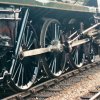

Last edited:
spikey faz
Western Thunderer
Those valve guide castings look the same/very similar to the ones that came with my Crosti kit. I replaced them with Ragstone castings, which are much better.
Mike
Mike
Bulldog3444
Member
oldravendale
Western Thunderer
Dave Holt
Western Thunderer
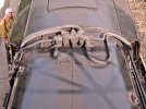
A bit odd at first glance. I imagine that the lower part of the backing plate and the steps themselves are the same distance from the loco centreline. Vertical on the near side (as normal) but, presumably, cranked out at the top on the firemans side to clear the injector pipework?
Dave.
Dave.
adrian
Flying Squad
Without knowing the specific details of the class that certainly seems to be the impression I get. The centre line through the cylinder bores I would typically line up close to the axle centre line of the wheels they are driving. It maybe the photo is misleading but they do look a little too high in the alignment.I wonder if that means I got the cylinder angle slightly wrong, so I'll check that out today and adjust if necessary.
I would agree - not only for the conn rods but coupling rods as well. They really are beefy lumps of steel, etched rods always benefit from additional washers soldered on front and rear to bulk them up.Peter, Hello. Looking at the rods, I feel they'd be improved by "beefing up" the bosses?
P A D
Western Thunderer
Peter,
One point to note on the 82xxx tanks is the cab footsteps. While those on the off side bend in under the cab, those on the near side run down vertically, as shown in the attached photograph of 82002 (copyright unknown).
Ian
Hi Ian,
I completely overlooked the difference in the cab steps. I must be getting less observant in my old age! I assumed that they were originally built with the turn in at the top on both sides and some received straight steps on both sides later on. I will correct it . Many thanks.
I would agree. The straight steps are set inboard of the lower edge of the cab and the injector pipework loops up behind step plate on the other side, which precludes mounting the step plate in the same place as the left hand sid Hence it is mounted further out and cranked inward under the pipes, no doubt to clear platform edges and remain within the loading gauge.A bit odd at first glance. I imagine that the lower part of the backing plate and the steps themselves are the same distance from the loco centreline. Vertical on the near side (as normal) but, presumably, cranked out at the top on the firemans side to clear the injector pipework?
Dave.
Mike, replacing the valve guided castings is an option but I decided to see what I could make them.
Regarding the commdnts on the conn rods and coupling rods, point taken.
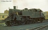
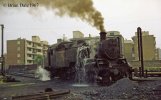
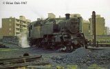
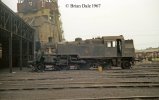
Brian, many thanks for the images. Sad to see the class 3s in such run down conditions.
Having removed the conn rod to add the missing overlay to the boss, I decided to drill some holes in the top hat bush to allow easier tightening and loosening while I'm setting up the valve gear, although its prob6time I added the return crank.
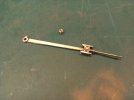
Although I'd removed the flats from the 8BA spacer which improved the appearance, as Paul suggested, nickel silver would look better. The problem was, what to make it from. I dug out my box of spare parts accumulated over ten years of collecting drawing instruments and found this leg extension from a Riefler compass. It's about 4 inches long and is hollow at the slotted end to a depth of about 3/4 inch to accept the peg of what ever attachment you are using (needle, pen or pencil). It is about 5mm in diameter so just about right to make a new spacer.
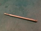
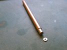
After sawing off the hollow section, squaring up the end and drilling out 2.5mm on the lathe, I sawed off two circles about 2mm wide then sanded to size. Much better than the brass one and it gives the impression that the centre boss on the coupling rod and inner face of the conn rod are wider than they actually are.
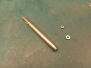
To thicken the fork end of the rear coupling rod and cover the unsightly etched groove on the outer face, I made an "overlay" from the another compass leg extension after first turning it down to match the fork diameter. I then drilled out the end to clear 12 BA before sawing off 2 circles and sanding to size as before.
Here's the results. I also used a 14BA nut drilled and tapped 12BA to retain the screw. I used a 12BA screw as the etched holes were too large for 14BA, but a 12BA nut is too large in appearance.
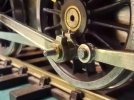
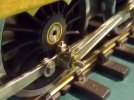
The rods are no longer parallel but it's not noticeable from normal viewing angles and it still runs smoothly.
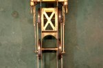
This closer view was taken before I'd thickened the fork end boss and replaced the 12BA nut.
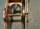
I'm leaving the front and rear bosses on the coupling rods as they are. The front one matches the prototype which is of reduced thickness for clearance purposes behind the the crosshead. If I thicken the rear ones I'll have to replace the the screws and the top hat bushes so I'm living with it as is.
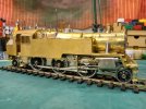
Some adjustment of the cylinder angle was possible so the conn rods clear the slide bars equally at tdc and bdc and I've now added the motion brackets, but the left hand footstep has still to be modified. Oh, and I've also removed the front valve covers, cut about 1.5mm off the rear and refitted. These were too long and the front edge was too close to the drop plate. I've had to replace the tail rods as they were now too short after having cut them back to clear the drop plate when the valve covers were the original length.
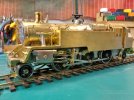
Without knowing the specific details of the class that certainly seems to be the impression I get. The centre line through the cylinder bores I would typically line up close to the axle centre line of the wheels they are driving. It maybe the photo is misleading but they do look a little too high in the alignment.
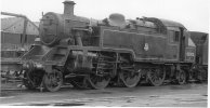
Adrian, if you look at this image posted above by Paul Tomlinson, I dont agree that the cylinders are too high. They are very tight against the hanging plate as on the prototype. By the way look at all the leaks in the side tank, a problem for which the class was prone. Hope the new build guys have taken this into account and taken steps to prevent it on 82045!
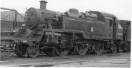
Cheers,
Peter
P A D
Western Thunderer
I mounted the rest of the valve gear apart from the eccentric rods and return cranks on the cylinder/slidebar unit after adding a cross brace to the top of the slide bars.
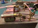
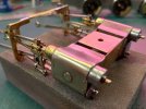
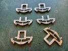
Next the driving wheel springs and hanger castings. The one bottom right is how they come, but they need modifying for each axle to clear other fittings. First the ledge at the bottom of the outer face of the horn blocks on all the castings needs to be removed. I sawed them off first then finished off with a file and sand paper. At the top the rear castings need an area of the rear hanger removed to clear the stretcher for the rear truck. The middle ones are for the centre drivers and need the top removing to allow the control spring to reach the top of the axle bearings. At the bottom are the castings for the front drivers. To clear the stretcher for the front truck they need to be modified as per the one on the left.
To solder them to the frames I clamped them in place using mini clothes line pegs from Hobbycraft. For a couple of quid you get a bag full. I used 145 solder to do it and the trick is to add plenty of flux so the solder flows well and only touch the nickel silver with the iron not the white metal. The centre axle spring had already been fitted.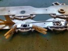
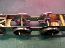
To set the return cranks on the reversed top hat bushes, I first screwed the outer bush tight against the inner bush and marked where the top of the crank should point. The bush was then soldered to the rear of the crank aligned with the index mark.
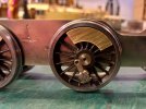
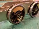
To attach the eccentric rod to the return crank I used a counter sunk 10 BA brass screw. I counter sank the outer face of the boss on the rod, as well as turning down the screw head to get a near flush fit, to avoid fouling the bearing cover. The rods were oiled at the joint and then the outer face cleaned before carefully soldering the bearing cover in place.
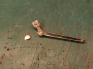
Here's one completed. The washer is used as a spacer between the rod and the crank to ensure sufficient clearance. I've had the sprue of roller bearing return crank covers for years, but I don't recall where I got it from. I think there were dozen when I first got it.
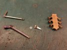
Much better than the wafer thin etch parts that come with the kit.
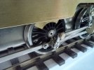
At the other end of the eccentric rod I used 1.3mm NS rod soldered on the inside face only. I blacken the moving part with a permanent marker to avoid locking up the joint. 1.3mm rod was used in all the other oversize holes in the valve gear.
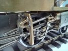
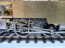
Here's a view of the completed gear after adding the lifting link and shaft. I note that 82045 will have an LMS 4 bolt fasting and plain bearing rather than the forked type fastening and roller bearings of the originals. I believe it is a more secure and efficient type of fastening so maybe it is for reduced maintenance reasons? The kit does not provide any parts for the cross shaft supports so I'll have to knock something up for those.
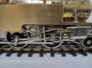
And t'other side. The scratched up drop links are located with a 0.8mm rivet soldered to the link and then glued into a hole in the crosshead. If I'd soldered it in place it would have been a pajn to clean up and it's secure. Note that I've added some tiny glass beads to the recessed drilled into the drop link which gives an impression of the fastenings.
Up top I've added the lifting brackets and inspection cover (scratch) to the left hand tank top.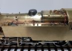
And the same on the other side as well as the fire iron stowage brackets.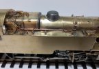
Cheers,
Peter


Next the driving wheel springs and hanger castings. The one bottom right is how they come, but they need modifying for each axle to clear other fittings. First the ledge at the bottom of the outer face of the horn blocks on all the castings needs to be removed. I sawed them off first then finished off with a file and sand paper. At the top the rear castings need an area of the rear hanger removed to clear the stretcher for the rear truck. The middle ones are for the centre drivers and need the top removing to allow the control spring to reach the top of the axle bearings. At the bottom are the castings for the front drivers. To clear the stretcher for the front truck they need to be modified as per the one on the left.

To solder them to the frames I clamped them in place using mini clothes line pegs from Hobbycraft. For a couple of quid you get a bag full. I used 145 solder to do it and the trick is to add plenty of flux so the solder flows well and only touch the nickel silver with the iron not the white metal. The centre axle spring had already been fitted.


To set the return cranks on the reversed top hat bushes, I first screwed the outer bush tight against the inner bush and marked where the top of the crank should point. The bush was then soldered to the rear of the crank aligned with the index mark.


To attach the eccentric rod to the return crank I used a counter sunk 10 BA brass screw. I counter sank the outer face of the boss on the rod, as well as turning down the screw head to get a near flush fit, to avoid fouling the bearing cover. The rods were oiled at the joint and then the outer face cleaned before carefully soldering the bearing cover in place.

Here's one completed. The washer is used as a spacer between the rod and the crank to ensure sufficient clearance. I've had the sprue of roller bearing return crank covers for years, but I don't recall where I got it from. I think there were dozen when I first got it.

Much better than the wafer thin etch parts that come with the kit.

At the other end of the eccentric rod I used 1.3mm NS rod soldered on the inside face only. I blacken the moving part with a permanent marker to avoid locking up the joint. 1.3mm rod was used in all the other oversize holes in the valve gear.

Here's a view of the completed gear after adding the lifting link and shaft. I note that 82045 will have an LMS 4 bolt fasting and plain bearing rather than the forked type fastening and roller bearings of the originals. I believe it is a more secure and efficient type of fastening so maybe it is for reduced maintenance reasons? The kit does not provide any parts for the cross shaft supports so I'll have to knock something up for those.

And t'other side. The scratched up drop links are located with a 0.8mm rivet soldered to the link and then glued into a hole in the crosshead. If I'd soldered it in place it would have been a pajn to clean up and it's secure. Note that I've added some tiny glass beads to the recessed drilled into the drop link which gives an impression of the fastenings.

Up top I've added the lifting brackets and inspection cover (scratch) to the left hand tank top.

And the same on the other side as well as the fire iron stowage brackets.

Cheers,
Peter
Last edited:
P A D
Western Thunderer
I ran out of images last night but here are a couple of other details that were added.
The fixings for the lifting brackets in the bunker.
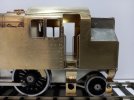
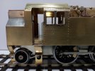
And the covers on top of the cylinders.
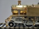
I still need to make and add the flange around the bottom edge.
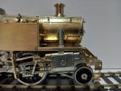
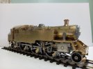
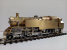
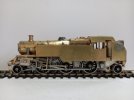
And a "walk around showing the state of play so far.
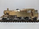
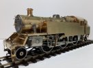
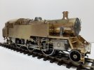
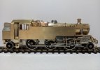
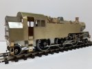
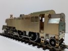
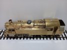
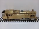
Cheers,
Pete
The fixings for the lifting brackets in the bunker.


And the covers on top of the cylinders.

I still need to make and add the flange around the bottom edge.

And a "walk around showing the state of play so far.


Cheers,
Pete
P A D
Western Thunderer
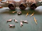
Brake rigging next. Here's what you get in the kit. White metal hangers, crank/mount and cross beams (not shown). Also included are these cast brass cross beams which although incorrect, as is the brake crank mount, I decide to use with some modifications to give a more robust set up. Note the size of the pin on the brake hangers compared to the massive mounting holes in the frames!
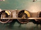
I plugged the front and middle frame holes with tube inserted the across the frames and removed the white metal pins on the hangers, drilled out and replaced with 1mm NS rod.
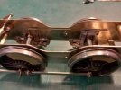
For the rear hangers, I couldn't use tube across the frames as this would not allow the motor to be fitted, so I plugged the holes with Slaters top hat bushes fitted with the flange inside, trimmed and filed flush on the outside. The pins on the hangers were replaced with 1.2mm NS rod to suit the hole size in the bush.
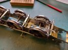
The pull rods I made from 0.9mm NS rod, annealed and flattened at the ends and drilled to match the holes in the modified brass cross beams.
Here's the front section completed. As there are two pull rods either side there is no interference with the screw for attaching the front truck. That won't be the case at the rear where there is a single central rod.
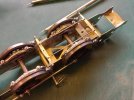
This is the shackle for the rear cross beam being "forged" from 2mm NS rod. I annealed first then clamped in parallel jaw pliers, squeezed to start the flat, then hammered the crap out of the top of the pliers to produce the required flat. This required 4 or 5 annealings and hammering sessions to get the required flat. I then held the produced flat in pliers to anneal the other end before returning to the parallel pliers to produce another flat at 90 degrees to the first.
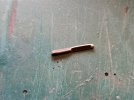
After fettling up and drilling, making another pull rod and fitting, you get this. The instructions tell you to add another spacer ahead of the rear truck mount to fix the spurious crank but this is incorrect as the crank needs to be further back behind the truck mount.
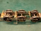
This is the replacement crank and frame under construction.
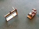
And completed. The cylinder was turned up on the lathe from NS drawing instrument spare parts. The top is from a thumb wheel and you can still see some of the grips.
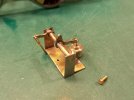
And the additional spacer added behind the rear truck mount. The turn buckle was made from tube and 10 BA nuts and the rod from the crank is inserted in the tube and the unit screwed to the spacer.
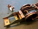
And the completed brake rigging. The rear pull rod etc if not detachable would prevent the fitting and removal of the rear truck.
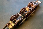
It's a bit of a fiddle to get the truck screw in but nothing untoward.
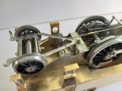
The sand boxes are also incorrect and required modifications to get them to look more like those on the prototype.
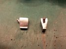
They come tapered on the front and rear faces but should have a vertical face at the rear. I soldered them to brass strip and filled the gaps with Isopon car body repair filler.
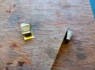
Here they are part way through the process.
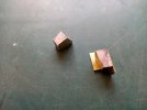
And ready for fitting with the sand pipe castings (Laurie Griffin) in place.I added fixing pins to the inner faces to aid location. The filler lids were turned from brass rod, the left one is flush fit with the box top, but the right one has a neck to clear pipe work.
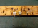
I've run out of images. To be continued....
Peter

I plugged the front and middle frame holes with tube inserted the across the frames and removed the white metal pins on the hangers, drilled out and replaced with 1mm NS rod.

For the rear hangers, I couldn't use tube across the frames as this would not allow the motor to be fitted, so I plugged the holes with Slaters top hat bushes fitted with the flange inside, trimmed and filed flush on the outside. The pins on the hangers were replaced with 1.2mm NS rod to suit the hole size in the bush.

The pull rods I made from 0.9mm NS rod, annealed and flattened at the ends and drilled to match the holes in the modified brass cross beams.

Here's the front section completed. As there are two pull rods either side there is no interference with the screw for attaching the front truck. That won't be the case at the rear where there is a single central rod.

This is the shackle for the rear cross beam being "forged" from 2mm NS rod. I annealed first then clamped in parallel jaw pliers, squeezed to start the flat, then hammered the crap out of the top of the pliers to produce the required flat. This required 4 or 5 annealings and hammering sessions to get the required flat. I then held the produced flat in pliers to anneal the other end before returning to the parallel pliers to produce another flat at 90 degrees to the first.

After fettling up and drilling, making another pull rod and fitting, you get this. The instructions tell you to add another spacer ahead of the rear truck mount to fix the spurious crank but this is incorrect as the crank needs to be further back behind the truck mount.

This is the replacement crank and frame under construction.

And completed. The cylinder was turned up on the lathe from NS drawing instrument spare parts. The top is from a thumb wheel and you can still see some of the grips.

And the additional spacer added behind the rear truck mount. The turn buckle was made from tube and 10 BA nuts and the rod from the crank is inserted in the tube and the unit screwed to the spacer.

And the completed brake rigging. The rear pull rod etc if not detachable would prevent the fitting and removal of the rear truck.

It's a bit of a fiddle to get the truck screw in but nothing untoward.

The sand boxes are also incorrect and required modifications to get them to look more like those on the prototype.

They come tapered on the front and rear faces but should have a vertical face at the rear. I soldered them to brass strip and filled the gaps with Isopon car body repair filler.

Here they are part way through the process.

And ready for fitting with the sand pipe castings (Laurie Griffin) in place.I added fixing pins to the inner faces to aid location. The filler lids were turned from brass rod, the left one is flush fit with the box top, but the right one has a neck to clear pipe work.

I've run out of images. To be continued....
Peter
P A D
Western Thunderer
The sandboxes were mounted in holes drilled in the frames. Masking tape was used to mark the position.
And then the boxes were epoxied in place.
After trimming and angling the pipes. I've still to make and add the support brackets to the ends of the the pipes.
On the left hand side I have now straightened the backing plate to the footsteps and remounted.
To fit the truck it is first threaded onto the rear pull rod.
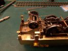
And then the brake cylinder subsection is located and fixed with a screw from above, before the truck is inverted and the screw added.
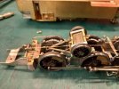
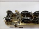
Not too shabby a representation of the brakd gear methinks.
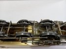
The gaps lower down are starting to fill up now. The injectors and pipework should be fun and of course I've still to make the support bracket for the weight shaft and lifting links.
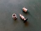
This is one of the buffers from Invertrain that I'll be using, with a couple of the poor castings that came with the kit. The holes in the stocks are way too large for the diameter of the shanks on the buffer heads that were provided. The Invertrain buffers are not perfect but much better than the Kit ones.
Cheers,
Peter

And then the boxes were epoxied in place.

After trimming and angling the pipes. I've still to make and add the support brackets to the ends of the the pipes.

On the left hand side I have now straightened the backing plate to the footsteps and remounted.

To fit the truck it is first threaded onto the rear pull rod.

And then the brake cylinder subsection is located and fixed with a screw from above, before the truck is inverted and the screw added.


Not too shabby a representation of the brakd gear methinks.

The gaps lower down are starting to fill up now. The injectors and pipework should be fun and of course I've still to make the support bracket for the weight shaft and lifting links.


This is one of the buffers from Invertrain that I'll be using, with a couple of the poor castings that came with the kit. The holes in the stocks are way too large for the diameter of the shanks on the buffer heads that were provided. The Invertrain buffers are not perfect but much better than the Kit ones.

Cheers,
Peter
Last edited:
Tim Humphreys ex Mudhen
Western Thunderer
Peter,
Are you going to fit the lubricators to the front of the footplate, either side of the smokebox?
Tim
Are you going to fit the lubricators to the front of the footplate, either side of the smokebox?
Tim
P A D
Western Thunderer
Of course Tim. There's still lots more to add, some castings and some scratch.Peter,
Are you going to fit the lubricators to the front of the footplate, either side of the smokebox?
Tim
Cheers,
Pete
Why not go for the MOK buffers. About the best for the standards.The sandboxes were mounted in holes drilled in the frames. Masking tape was used to mark the position.
View attachment 201183
And then the boxes were epoxied in place.
View attachment 201185
After trimming and angling the pipes. I've still to make and add the support brackets to the ends of the the pipes.
View attachment 201178
On the left hand side I have now straightened the backing plate to the footsteps and remounted.
View attachment 201180
To fit the truck it is first threaded onto the rear pull rod.
View attachment 201181
And then the brake cylinder subsection is located and fixed with a screw from above, before the truck is inverted and the screw added.
View attachment 201182
View attachment 201187
Not too shabby a representation of the brakd gear methinks.
View attachment 201188
The gaps lower down are starting to fill up now. The injectors and pipework should be fun and of course I've still to make the support bracket for the weight shaft and lifting links.
View attachment 201189
View attachment 201190
View attachment 201192
This is one of the buffers from Invertrain that I'll be using, with a couple of the poor castings that came with the kit. The holes in the stocks are way too large for the diameter of the shanks on the buffer heads that were provided. The Invertrain buffers are not perfect but much better than the Kit ones.
View attachment 201191
Cheers,
Peter
Nick

