TheSnapper
Western Thunderer
When a friend asked me to install a sound decoder into his 0 Gauge Heljan Railbus, I thought, OK, this is a quick simple job – a plug-in 21-pin decoder, space already for ESU 23mm speaker, room in the roof for a stay-alive unit (which is really is really essential for this 4-wheeled vehicle).
I was wrong, of course; it turned out to be a bit more involved and time-consuming.
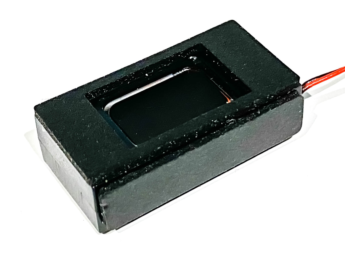
Beneath the driver’s cab at one end, there is a removable cover which reveals the chamber ready to accept an ESU 23mm speaker.
.jpg")
The instructions for fitting the speaker indicate that at the same end there is a small hole in the inner roof, leading to a conduit in the driver’s cab down which wires can be fed into the speaker chamber.
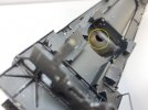
First of all I couldn’t find the conduit; I had to line-up it up with the hole, by tweaking the position of the driver’s compartment. I then found that there was no way through the floor into the speaker chamber. So using the sharp end of a scalpel & a pointed grinding tool in the Dremel I carefully created a small opening. I then used a length of brass rod to poke a way through.
.jpg")
.jpg")
The speaker wire needs to be very fine as there ain’t much room for thicker stuff through the conduit. I soldered the 2 ends of a loop of ESU Decoder Wire (part # 51940 - 51949) to the end of the brass rod & pulled it through, like a thread on a needle.
.jpg")
Hopefully the photos will explain better than words.
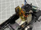
After removing the blanking plug, the decoder fits easily. I used a Zimo MX644D from Digitrains, loaded with their AC Railbus sound project, created by Paul Chetter.
.jpg")
Next problem is where to attach the speaker wires at the decoder end. Usually there are 2 solder pads or holes on the native PCB, but nothing was obvious.
Research required – Google-is-your-friend time!
I discovered that Paul Chetter had written an article on installing sound decoders for both the 00 gauge & 0 Gauge versions of the Heljan Railbus, in Hornby Magazine for October 2015. Not having the magazine, I dug further into the Internet & managed to download a PDF copy from PDF Magazine Download - Catalog popular PDF journals . I chose the free download, which was quite slow; I believe you can subscribe for a quicker service if required.
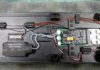
This showed me all I wanted to know. There is a micro-socket on the board labelled CN6 which is for the speaker wires. Problem is there is no plug supplied! And if there would have been, it would be nigh impossible to connect wires to it, as it would be too tiny. A plug with a couple of flying leads to connect to would have been ideal (I did once try to source some of Heljan’s plugs & sockets, but they would only sell me 10,000!).
.jpg")
The answer revealed in Paul’s article was to solder directly to the base of the relative pins on the decoder connection. This was very tricky and needed a steady hand and a fine bit on the soldering iron. After a couple of attempts, I managed to do it, making sure there were no bare wires shorting, which would have been disastrous to the decoder.
.jpg")
The holes & openings in the speaker enclosure were sealed and the unit wired-up and installed on the underside of the chassis.
.jpg")
Fitting the stay-alive unit (a compact Zimo SC68 unit) was straightforward – it solders directly to 2 pads on the decoder. Just need to make sure the wires are fitted the correct way around! I insulated the casing with shrink-wrap, and fixed it to the roof with double-sided tape.
And so to testing. Although the overall sound was really good, I found that with the default decoder settings I couldn’t get the characteristic gear-changes to occur until the Railbus was going too fast. There are 4 changes in all.
The ever-helpful Mr Chetter replied to an enquiry I posted on “the other place”, to say that it is possible induce a gear change when the engine idle sound or the cruising sound is playing, by reducing the throttle and immediately increasing it again, just like you would when driving a car.. The gear change will occur, followed by acceleration sounds.
However, I wanted the gear-changes to sound automatically within a reasonable speed range, without having to fiddle with the throttle. I tried lowering the maximum speed (CV5), changing the momentum (CV3 & CV4) and using Decoder Pro to change the speed curve, without too much success.
The breakthrough came when Paul suggested I adjusted CV57, which according to the Zimo manual, reduces top speed by reducing the voltage to the motor and effectively 'compresses' the gear changes into a lower speed range.
CV57 changes certainly made the difference - I can now get the full 4 gear changes automatically in about 15ft of test track, without adjusting the throttle.
These are the settings I ended up with
CV 57 set low to =30
CV3 = 50
CV4 = 60
CV5 =1 (=255, default)
CV6 - 120 (default)
I also used Decoder Pro to set the speed curve to a log curve.
See here for information on setting speed curves using Decoder Pro:
Comprehensive Programmer - Speed Control Pane
Of course these settings may change slightly as time goes by, but it’s a start!
….and then we had another problem, or rather 2 problems.
On the layout, the Railbus kept derailing when negotiating point-work. Initially we thought it was due to the long rigid wheelbase, through admittedly tight check-rails, but when checked against a BR Mk1 Horsebox, it was virtually the same. Also the lights both back & front kept flickering on & off, no matter which direction the model was running.
Eventually we checked the back-to-back measurement and it was quite a way out on both wheels. In fact one was worse than the other. So we removed the keeper plates, extracted the wheelsets and managed to carefully persuade them outwards to the required 29mm.
On replacing the wheels, we ensured that the pickups were making really good contact, as we suspected this was the cause of the flickering lights.
Testing again on the layout point-work, all was well and gone were the flickering lights. My friend is pleased.
Anyone else had problems with Heljan back-to-back measurement?
.JPG")
.JPG")

.JPG")
.JPG")
.JPG")
.jpg")


.jpg")
.jpg")
.jpg")

.jpg")


.jpg")

.jpg")