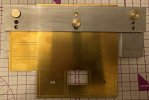
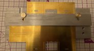
7mm OzzyO is back building a Dave Parkins' kit (and some JLTRT Coaches as well). Now on to some MMP 16ton wagon kits.

michael080

Western Thunderer
I've also got the cover glasses on order. But the problem with the cover glasses is the size about the largest that I saw were 24 X 24mm, not quit big enough for a Mk1 window and definitely not big enough for a Mk2 window. As the real Mk1 window were in five panes of glass with the bottom pane being set at one angle and the top four at another angle I'm going to see if I can get the affect on the model. Now for a question, were the window in a BG the same?

I built a MMP BG1 a couple of years ago and found a lot of useful pictures, including htis one.

IMG_1832.jpg.8a40410208ad6a12f149db6495b6e353.jpg

It looks like the window glass has an angle between the upper and lower part, so your assumption is probably correct.

Michael
 

40057

Western Thunderer
Hello Michael,

I've also got the cover glasses on order. But the problem with the cover glasses is the size about the largest that I saw were 24 X 24mm, not quit big enough for a Mk1 window and definitely not big enough for a Mk2 window. As the real Mk1 window were in five panes of glass with the bottom pane being set at one angle and the top four at another angle I'm going to see if I can get the affect on the model. Now for a question, were the window in a BG the same?

Onto the B4 bogies with a coat of paint on them.
View attachment 186251

You can see what I've done to add some strength to the top beam. it was getting a length of 1mm N/S in the channel and filling it with super glue jell. Lets see how it works. I've got some more on order but I've got a better idea for them.
View attachment 186253


Under coat on the springs and axle box covers.
View attachment 186256

And top coat on.
View attachment 186258

The ETH gear that I'll be using from PRMRP products.

View attachment 186260

Now onto one of the coaches a JLTRT Mk1 CK. Not a lot to out of the ordinary yet. Apart from using two vee hangers, the inside one should get cut back to the angle trussing.
View attachment 186261

Buffers in place and the channel to clear the spring for the draw gear milled out, I'm going to use the Ellis Clarke drop head buckeye couplings on this coach.
View attachment 186262

You can just make out the pins that I've used to help add some strength to the joint between the trussing and the floor pan. After doing a few JLTRT coaches it dawned on me that the small bit at the ends of the trussing should be folded the wrong way so you get what looks like a channel.
View attachment 186263

While I was on the bay of E I decided to have a look for a set of Maun parallel jaw pliers and I came across these for about £13.50. So I got a set with the brass inserts and a set with the normal steel jaws.
View attachment 186264

ATB

OzzyO.
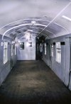
Were the windows in the BG the same?

Yes.

The Mk1 body shell was highly standardised and all types were built of essentially the same components.
 
Test Track

OzzyO

Western Thunderer
Hello all,

OzzyOs back. First why I've not been posting much the computer had a funny turn, I thought that I was doing a back to a system restore point but it just about wiped out the hard drive.
Then my back started giving me jip, after some prodding and poking X-rays and scans it turned out that I had three compression fractures of three vertebra ( V1, V2 & V3) nice (not), all brought on with osteoporosis.

I've had a good time on the bay of E spending lots of money, these are some of the first bits and how I'm going to use them.

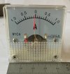
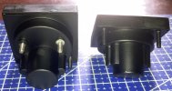
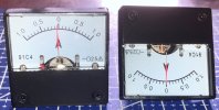
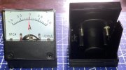
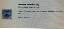
The first bit of kit is an ammeter that reads in both directions, as bought.
Ammeter 01.JPG

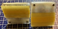
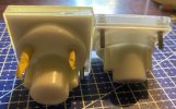
And masked off.
Ammeter 03.JPG
Ammeter 02.JPG

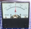
A coat of black paint applied.
Ammeter 01a.JPG
Ammeter 02a.JPG
Ammeter 03a.JPG

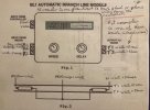
How I'm looking to fit the ammeter into the test track circuit using the white + green so that the power runs through the ammeter.
Shuttle unit 04.JPG

A photo showing the automatic branch line module showing the white + green wire.
Shuttle unit 02.JPG

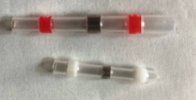
I'm going to use these to join the wires they are shrink to fit with a band of solder in the middle, I'll let you know how I get on latter.
Shuttle unit 03.JPG

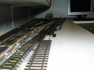
Just to remind people how the test track looks, it has two separated tracks the one on the left is just powered just by the controller and the points are powered by the good old finger (the middle finger is not compulsory, but can be use when things are not going well).
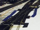
The track on the right is powered using the branch line module. When this photo was taken the double slip was finger powered it now has a control box to throw the point blades (thanks Ian for the circuit drawing). It works so that a full circuit the loco will go through all four moves. Or the automatic point circuit can be switch out and only use one set of tracks.
DSCF0452.JPG
DSCF0453.JPG

The slip is powered by two Peco surface mounted point motors, IIRC in the box of tricks there are two capacitor discharge units, that's about all I can remember apart from four reed switches in between the rails.

More to follow soon,
OzzyO.
 
Last edited:
Test Track

OzzyO

Western Thunderer
Good to see you back Ozzy, and so sorry to learn about those fractures. Not good news indeed. I'm sure I join others in hoping that you have that under control now and that the dry wit will flow...

Brian
Hello all,

somebody once said to me that if whit was s4!t I'd be constipated, the whit will be dry as I'm not allowed to drink with some of the medications that I'm on.

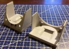
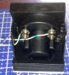
I've made two brackets for the ammeter to fit on out of plasticard I should have made the four sides about 4mm deeper before I fitted the base., then I would not have had to carve out so much to get the ammeters to fit.
Base unit 01.JPG
Base unit 02.JPG


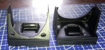
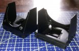
Then it was out with the satin black paint to get them looking something like.
Base unit 03.JPG
Base unit 04.JPG


At least when the meter is in place you can't see all of my cock ups. Well not to many of them.
Base unit 05.JPG

ATB

OzzyO.
 

OzzyO

Western Thunderer
Hi OzzyO
Do you have a link please to the ammeter?
Many thanks
Mark
Hello Mark,

I hope that this helps, it's on the bay of E, the price looks to be reasonable to me.
IMG_9727.JPG

Found some more one price looks good. I'll let you make your mind up on the rest.
IMG_9728.JPG
IMG_9731.JPG
IMG_9732.JPG


HTH

OzzyO.
 
Last edited:

daifly

Western Thunderer
Links to similar products:


Dave
 

simond

Western Thunderer
I’m astonished these things are still available.

If you want to do easy block instruments, then a centre-zero milliammeter is an excellent starting point.
 

OzzyO

Western Thunderer
Hello all,

back onto the ammeters this one is for the shuttle track but I've gone for white with blue hoops. With the wires coming out of the side,
Base unit 06.JPG

This is the reason for the wires to come out of the side one wire will run directly to the shuttle track feed where you can see the white wire with blue hoops and the other one will join onto the one that comes out of the shuttle unit now. this will be the first use of the white shrink to fit connection with the solder in it.
Shuttle unit 02 - Copy.JPG

The next one is for the direct to track feed from the controller, I don't know what colour the feed wire is, so I've just picked on orange with white hoops.
Base unit 07.JPG

As these wires come out of the bottom I had to do a bit of thinking about it and came up with just cutting two small slots in the double sided foam should work.
Base unit 08.JPG


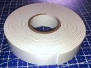
This is the double sided foam that I'm using it's 18mm wide and 2mm thick, I'm hoping that it will work Ok after all the years I've had it in stock.
Base unit 09.JPG


ATB

OzzyO.
 

OzzyO

Western Thunderer
Hello all,

to keep all the work on the lath and mill in one spot I'm going to put it all in my lathes and M/C tools thread in area 51.

ATB

OzzyO.
 

OzzyO

Western Thunderer
Hello all,

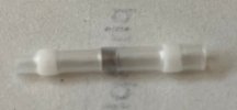
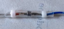
this is the first one of the heat shrink fastening with the solder in it.
Base unit 10.JPG

I could not find my hot air ( I know some of you will say I've get enough) gun so I used my micro flame torch.
Base unit 11.JPG

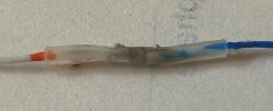
Well it sort of worked but the tube set on fire. But I did have a soldered joint. Time to buy a new hot air gun.
Base unit 12.JPG

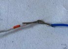
This time I am ready to try the full Monty, first the wires are twisted together.
Base unit 13.JPG

Getting ready for the heat.
Base unit 14.JPG

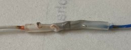
The heat has been applied, to the tube but the tube doesn't shrink as quick as what I'm use to but if you leave it for a minute or two it looks Ok.
Base unit 16.JPG

and from the other side.
Base unit 17.JPG

Now to do a couple more to see how I get on.

ATB from a sunny Barrow.

OzzyO.
 

OzzyO

Western Thunderer
Hello all,

I'm going to do this in two parts as it's quite heavy on photos.
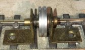
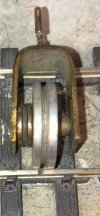
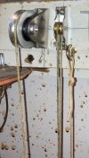
The old top wheels, the large one is 0.85" dia. and the small on is 0.4"dia. both these measurements are to the bottom of the V groove.
Drawbar pull old 2.JPG

The bottom bracket the wheel sizes are 0.85" and 0.4".
Drawbar pull old 3.JPG

The top bracket when it has been removed.
Drawbar pull old 6.JPG

The bottom bracket when it has been removed.
Drawbar pull old 5.JPG

Part two coming soon,

ATB

OzzyO.
 

OzzyO

Western Thunderer
Hello all,

Part two is about to start, this part is about the new wheels and pulley.

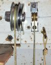
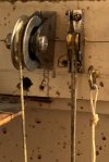
The new top wheels the large one is 1" dia. at the bottom of the groove the small one is 0.3" dia. at the bottom of the groove.
Drawbar pull 1.JPG
Drawbar pull 3.JPG
Drawbar pull 4.JPG

A drawing of the small wheel that's at the top.
Drawbar pull 8.JPG

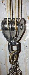
The bottom pulley the wheels are 0.45 dia. at the bottom of the groove.
Drawbar pull 5.JPG

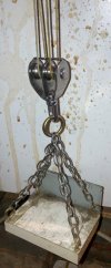
The bottom pulley showing the weight basket.
Drawbar pull 6.JPG

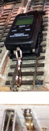
This is how I was taking the weight measurements at the top, the measurement gauge is for weighing luggage but it has a automatic lock feature when it gets to the maximum weight its lifting at the time.
Drawbar pull 7.JPG

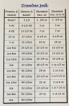
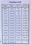
These were the drawbar pulls that I got for different weights the two columns that I used to make the graph were 2 & 3.Weights.JPG

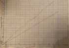
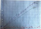
The one thing that I forgot to do was to do the full set of weight with the old wheels. But I have transposed all of the weight from column 3 on to a graph that is the green line, the blue line is with the old wheels.
If anyone wants to work out the pulley ratios, please go ahead and do so. The bit I find odd is at drawbar pull at the 10oz. mark where it dips down. The pencell line just below the green line is the straight line from zero to 23 1/2 oz.
Graph.JPG
ATB

OzzyO.
PS part three to follow soon.
 
Last edited:

OzzyO

Western Thunderer
Hello all,

after my last go at seeing what the weights to the drawbar relationship was I got some variations that I was a bit unsure of so I did it again.
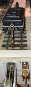
I this photo I used a coach under frame for the scale to ride on.
Drawbar pull 9.JPG

This is the results that I got in table form.
Weights 02.JPG

Then turned into a graph, the blue line is drawbar pull, the red one is the direct drawbar pull in theory. The black line is the old pulleys on a direct theory line.
Graph 02.JPG

ATB

OzzyO.
 
Last edited:

OzzyO

Western Thunderer
Hello all,

back to the shuttle unit, at the moment it's like working in slow motion, what should have taken an hour is taking an afternoon.

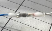
The heat shrink in use, it was only when I was editing the photos that I noticed that I had used a red heat shrink not a white one. When I come to testing it all if something is wrong this will be the first place that I will look.
Shuttle unit 05.JPG

Then it was trying to get the wire into this hole. I like the idea of the push down "plates" but when you have used them once the hole doesn't seem to open up the same as a new one.
Shuttle unit 07.JPG

I did sort of get the wire in place but I'm going to take a better photo just to see.
Shuttle unit 08.JPG

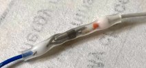
A close up of the heat shrink, the red bit (waterproofing) has expanded quite a lot bit it's a bit hard to tell if the solder has run. The joint feels ridged so it may have taken. Fingers crossed and any thing else I can cross, touch wood Etc..
Shuttle unit 9.JPG

ATB
from a grey and dim Barrow,

OzzyO.
 

OzzyO

Western Thunderer
Hello all,

I've been looking through Paul Bartlett's photos and spotted the following photos and have been wondering, how much work would be involved in converting a Modern Motive Power 16 ton steel mineral wagon with 8 shoe brake gear, or a 16 ton rebodied steel mineral wagon with 8 shoe brake gear.

This photo shows a R.C.H. vacuum with 4 shoes. For this wagon a MMP 16 ton 4 shoe mineral should fit the bill? Wagon number DB 567838.
IMG_9912.JPG

On this wagon I'm lucky enough to have a photo of both sides of the wagon. This is an ex Westinghouse air braked wagon. Now with double v hangers & clasp brakes. Wagon number DB126473

For this wagon I'm thinking about a 16 ton Mineral wagon with 8 shoes clasp brakes. I'm not sue if it should be a rebodied wagon or a wagon that's not had a new body? The rebodied wagon could have the body fitted the correct way around.
IMG_9913.JPG
IMG_9914.JPG

These are copyright to Paul Bartlett if Paul objects to their use I will remove them.
The photos are for showing the details of the brake gear and for no other use. If you want the full photos go to Paul Bartlett's photo web site.

If anyone has drawings of the air brake fittings it would help me a lot.

ATB

OzzyO.
 
Last edited:

OzzyO

Western Thunderer
Hello all,

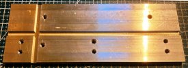
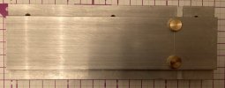
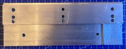
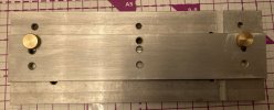
before I start on the spoil wagons I'm going to make a new Hold & Fold to do a bit more than the normal hold and fold will do. The first part to be machined up was the base plate 2 7/8" X 200mm X 1/4". With two 6mm X 3mmm slots machined in it, This is to take the top channel on the sides and end.
New hold and fold 01.JPG

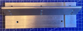
The clamp bar to hold the base while forming the base curve on the body end.
New hold and fold 02.JPG

The inside of the clamp bar, Note the slot at the L/H end.
New hold and fold 03.JPG


The slot was to take a length of N/S .7mm Dia. to get the clamp bar to get the force nearer to the body end. If it had been left as a flat plate the force would more than likely have been at the top of the body.
New hold and fold 04.JPG

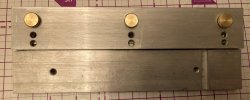
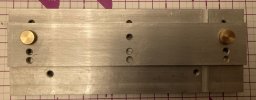
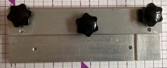
The main parts of the H & F in place this can be use for, filling the edges, bending the top channel and bending the bottom edge.
New hold and fold 11b.JPG
This was before I machined the small step in the top edge. This was also before I got some better finger wheels for tightening up the top plate.
New hold and fold 05.JPG

Showing the top plate in some of it's other positions.
New hold and fold 06.JPG
New hold and fold 07.JPG

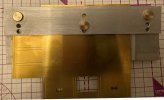
The step that's been machined on the top edge.
New hold and fold 11c.JPG
New hold and fold 11c.JPGNew hold and fold 11d.JPG
New hold and fold 12.JPG


Showing what the position of the side will look like for the first fold of the channel.
New hold and fold 09.JPGNew hold and fold 10.JPG

This is the position that I'll use for machining the odd spoil holes, doing this will mark the main plate that's why I'm doing it away from the main bending part of the H & F This will be done after the two channels are formed as I hope this will add a bit of strength to the sides.
New hold and fold 08.JPG

ATB

OzzyO.
 
Last edited:
Top