Mannin's whistle

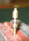
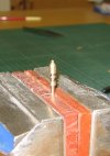
Which looks most like a whistle, they are both 20mm high approx which is 1' 3" scaled up.

  • Left

    Votes: 2 25.0%
  • Right

    Votes: 6 75.0%

  • Total voters
    8
  • Poll closed .

Martin Shaw

Western Thunderer
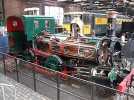
I posted a pic or two the other week of an IoM train circulating on my patio. Sometimes Accucraft in their desire to make an as accurate model as possible fall foul of full size hands and the whistle is a case in point. There is just in front of the cab a manifold on which the steam valves for the injectors are mounted and in between them is a whistle which is a brass casting which is screwed into the mounting plate by an M2 thread, and two bent brass rods purporting to be steam pipes. These need to be removed to take the boiler out and needed replaced, the whistle is prone to being caught, rags, hands whatever and because sections of the casting were so thin it bent are after sufficient straightenings had been made the inevitable happened and it snapped. I made a couple of new ones threaded 8BA and I have a poll for the preferred replacement, please vote for your choice and in due course a pic of the whole shebang will be forthcoming.
Thanks
Martin
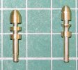
IMG_1883 (2).JPG
 

simond

Western Thunderer
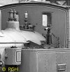
Might this help? (Wikipedia)

My impression is that the slot between the upper and lower bells is too wide. How you fix that without a thinner grooving/parting tool might be an issue.

hth
Simon

1685298966835.jpeg
 

Martin Shaw

Western Thunderer
Phil
Either or, neither is not an option and since most of it ends up black anyway I'm not too fussed to be honest. There is a fundamental design flaw in the model in that there is a significant gap between the boiler and the cab front, a missing top nut on the whistle is relatively insignificant but thanks for the pic.

Simon
Yes I think your probably right too and yes I'm at the limits of how I can hold things in the lathe and what I can practically do. Bear in mind that the bottom stem is 2.2mm in dia and has to be turned last otherwise it all just bends with tool pressure.

Edit:
Thinking about it, I need to do it again which I will tomorrow, this despite that need has been most helpful, second pair of eyes!
 
Last edited:

Martin Shaw

Western Thunderer
Thanks to all of you who expressed a view, and it's taken me longer than tomorrow however I did think more about Simond and Phil's comments. I can easily enough turn another and tighten it all up, although I am limited a bit by a parting/grooving tool 1.5mm wide. However given the main body is 4mm in dia turning the top knob is asking a bit too much, the remaining material is insufficiently robust to resist the cutting pressure of the tool and bendy bits will be the result. A further thought, whilst not protoypically accurate which sums up my modelling, why not have a nut hold the whistle body to the stem which happened a lot, the Victorian loco builders in Manchester just made it look more sinuos. Now a 14BA thread is 1mm in dia so I drilled the end of the whistle and inserted a bit of screw with a 14BA nut on it.
IMG_1884.JPG
It's fair enough and this is well blown up but it does look a bit too prominent so I took a 16BA nut, drilled it 0.8mm and tapped it 14BA and substituted it.
IMG_1888.JPG
Much better if fortuitously slightly out of focus. Anyway it will do and if no one's seen Phil's photo they won't know any better. Still got to make a new whistle!
Regards
Martin
 
Last edited:

simond

Western Thunderer
Martin,

it begs the question, why not make in two parts & screw the upper bell on? It would allow you get a narrower slot between upper & lower bell.

atb
Simon
 

Ian@StEnochs

Western Thunderer
Martin,

it begs the question, why not make in two parts & screw the upper bell on? It would allow you get a narrower slot between upper & lower bell.

atb
Simon

That is similar to what I do, albeit in 7mm scale, and soldered rather than screwed together. I turn the two parts separately and assemble onto a piece of brass wire. Brass wire is also less likely to break than free cutting brass if it gets knocked too.

Ian.
 

Martin Shaw

Western Thunderer
Simon
It only begs the question if it had even arisen in my mind, and whilst in principle it is a good idea things are getting pretty small and your rather over estimating my skills.

Ian
I am going to follow your suggestion, whistle and stem as one turning and a separate piece to represent the valve which can now be a tad smaller and therefore better in appearance, soldered on. This part is painted black eventually.

Thank you both for the helpful pointers.
Regards
Martin
 

PhilH

Western Thunderer
Martin,

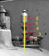
Whistle A.jpg

I did the whistle for my Accucraft C16 in two parts as Simon and Ian suggested, with the top section fixed in the bottom with a 12BA screw. One advantage in this case was that the top section could be removed to give a little more clearance in layouts with tunnels of restricted height.

While this may seem unduly complicated, if you want to make a reasonable representation of the valve below the whistle it could be done in several parts as below.

Whistle B.jpg

(1) coloured yellow is a brass wire of suitable diameter, providing a mounting spigot at the bottom.
(2) is a vertical piece of round section brass tube or turning.
(3) is a horizontal round of larger diameter than (2) to represent the valve, cross drilled for the wire.
(4) is a brass turning, and the joint between (2), (3) and (4) can be filled with solder.
(5) is the separate top section, glued or soldered on to the top of the wire.
 

Martin Shaw

Western Thunderer
I'll see if I've still got the bits of the original, it might illuminate things a bit. I fear this one off job might be growing longer legs than it deserves but thanks for the contributions. I nearly bought a C16 recently, probably a good thing I didn't really.
Martin
 

Martin Shaw

Western Thunderer
Just to round this off, here's what I ended up with.
IMG_1892.JPG

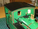
It's far from perfect, probably too conical however at a normal viewing distance it looks ok and the painted bits tend to make the whole thing less obvious. I have found that there is a discrepancy in measurements somewhere which makes the cab front higher than it should be, notice the gap between it and the boiler. I though it was my model however it is on all the ones I can identify on line. It again is not too noticeable until you put in the control rods for the injector steam valves and whistle when their uphill inclination to the cab becomes obvious, so I left them off. I should fill in the holes but hey ho. A coating of running muck and dirt from the garden will hide a multitiude of my sins. At least after nearly a year it can go into the toybox to be played with.

Meanwhile in the best engineering traditions the Lynton Baldwin has been dismantled,
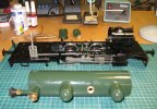
IMG_1893.JPG

principally to assess for fitting RC gear, but also to do one or two other critical jobs. Degunking it from the pool of steam oil acting as a slip hazard on all flat surfaces, and replacing all the soft brass M1.6 and M2 hex head screws that hold it together. Where possible they are replaced by 8BA CH or RH screws so that dismantling is a screw driver exercise rather than a dodgy sized nut runner that deforms the head making removal impossible. You might argue that it detracts from the model however they are on the underside of surfaces and with a touch of black paint are next to invisible. They do however make life so much easier, not that I anticipate taking things apart regularly. More when there's something more interesting to show.

Best wishes
Martin
 

simond

Western Thunderer
Martin,

it may be worth considering hex socket screws. It’s possible to get “ball drivers” which allow access at a slight angle, and eliminate the risk of the screwdriver slipping out of the slot, gouging paintwork and fingers.

I appreciate it’s a different beast, but converted nearly all the tired fittings on my old MotoGuzzi to socket screws. There are still a few to go…

atb
Simon
 

Rob R

Western Thunderer
Martin,

it may be worth considering hex socket screws. It’s possible to get “ball drivers” which allow access at a slight angle, and eliminate the risk of the screwdriver slipping out of the slot, gouging paintwork and fingers.

I appreciate it’s a different beast, but converted nearly all the tired fittings on my old MotoGuzzi to socket screws. There are still a few to go…

atb
Simon
Simon,
The problem with small "hex ball drivers", apart from damaging the hex hole with extended use over time, is their tendency to snap off at the slightest provocation- the undercut required to form the ball doesn't leave much meat on the shaft- and the hardened "ball" will enevitably jam in the hex hole leading to much muttering in anglo saxon.
I would be tempted to go with something like these:-Amazon Link

Possibly cutting a slot across the head to cover all bases.
Rob
(who has been chiselling the remains of said ball drivers - snapped by the previous shift:rant:- out of expensive bits of kit for the best part of 40 years)
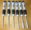
Edit Link Fixed.
 
Last edited:

Martin Shaw

Western Thunderer
I agree with both Simon and Rob, but!
I already have a large stock of suitable size and length BA screws, such that beyond my failing memory I'll never need to buy another one. Cap head screws have their uses, MotoGuzzi maybe but model steam engines representing Victorian engineering, probably not. I'm already pushing my luck with slotted round head ones as it is.

I have a set of not cheap ball ended hex drivers that sit behind the lathe or mill bench according to taste. They are probably ok if the cap head screws were made to the DIN spec which they invariably aren't so I have every sympathy with Rob's view, BTW the link appears not to work. These coincidentally arrived this morning, maybe they'll work better, he said hopefully.

Regards
Martin
IMG_1895.JPG
 
Top