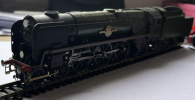
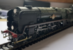
4mm Lyminster Junction

After many moons of thinking about it, collecting components, rolling stock, buildings, information and imagery, earlier this year I finally got underway on the 4mm model called Lyminster Junction, an imagineered alternative to Axminster. It is a junction on the Yeovil & Exeter section of the LSWR then Southern, then BR/SR. It is being constructed in a studio located over a double garage and utility room with eaves on each side of the floorspace which are to be used for 'off-stage' layout elements such as storage sidings.

The layout is planned to be operated in two periods. Firstly, pre-WWII circa 1935, with locos and rolling stock in the Maunsell olive green livery with rolling stock to suit, and secondly 1956, the year of my birth. Rule 1 applies, so to be seen in the future will be formations of more recent West of England trains hauled by Rebuilt Bulleid Pacifics, Warship diesels, Classes 33, 47 and 50.

In the grand scheme, LJ is the connection point of two branch lines which run to the coast. With a trailing connection to the junction one line leads to Lyminster, an equivalent of Lyme Regis in function. The other route also heads to the coast and terminates in what in reality is the Seaton area.

Construction so far has concentrated on one end of the layout where elevations of main line and branch plus the minimum 60" radius on the layout have to fit together with clearance of the timber roof supports. So far so good.

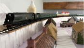
For the first time I have used Woodland Scenics dense styrofoam flexible track bed supports which has enabled me to trial the design using pins to hold the track bed support in place before applying adhesive and cork track bed. Similarly roads have been added and buildings placed to check for appearance. The constructed section presents a sweeping curve on an embankment that enters a rock cutting and short tunnel before entering the junction station area. This was a revised design where the mainline did not disappear under the eaves to re-emerge at the junction with sight of the train being lost for a lengthy section off-stage. The revision means it is possible to run a full 12 car train in full sight for 3 out of four sides of the room without seeing it negotiate tight radius curves.
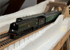
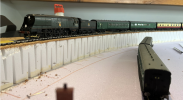
Screenshot 2023-06-17 at 5.49.10 PM.pngScreenshot 2023-06-18 at 8.55.40 AM.png

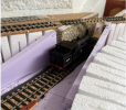
The first view is a mock-up of the scenic break to the junction station board. This is a very narrow section by necessity of providing access clearance for the stair well bannister. Originally the line was to go fully off stage under the eave but I decided on the narrow rock cutting approach to keep the train in continuous vision for longer, aiding the impression of distance on the approach to the junction. A road over-bridge could be an alternative to a short tunnel. A back scene board slots in behind the far styrofoam upright and I plan the intersection of foreground and background to be heavily foliaged. When all is complete I will add a fascia board of thin ply to neaten it all up. The tunnel mouth is made of chipboard sections with scribed DAS clay. The tunnel concept replicates Crewkerne Tunnel which was a mere 305 yards long. I presume this was a land owner requirement as otherwise opting up as a cutting would possibly make more sense.

The lower picture shows the embankment formed with dense styrofoam. It is seated on sheet styrofoam with a thin plywood under layer. Set 44 is shown in the original location for the branch. It will pass under the mainline. Its alignment has been changed since.
Screenshot 2023-06-27 at 6.25.05 AM.png

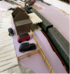
The branch runs in the foreground and after passing under the mainline enters a single platform halt. A leet passes under the branch just before a level crossing with the station road. Cutting down to the ply sheet provides the form for the water course. A siding is provided after the crossing which will add operational interest for trip working from the Junction.

The land forming in this area will be completed to give reason for the main line to swing left or 'south' and then go off-stage. Study of the Y&E routing shows that Joseph Locke made efficient use of the topography and in so doing incorporated numerous swinging curves avoiding the need to tunnel with a few exceptions, notably that of Honiton Tunnel and the steep approach gradient. The downhill rush from Honiton through Seaton Junction must have been spectacular in the day. I myself have witnessed a 47/7 in NSE days from the public footpath footbridge leaning into and out of the superelevation at full line speed. On my previous incarnation of Lyminster Junction it had a downgrade through the station (not really by design!) which also featured a sweeping 's' curve through the station with superelevation reversal. The effect was pleasing to the eye and the ear as a full 12 car rake clattered over the rail joints at speed. A touch of the Argo Transacord recordings there!

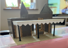
The Halt building is a much cut down Hornby 'Dunster' kit. A nice set of mouldings but it is over-scale necessitating using new doors with toplights as opposed to the mouldings provided. The canopy is formed using valence I had made by York Models for the Junction station which is modelled on Axminster itself. The cast columns are from cut down Hornby footbridge columns which are the correct profile for LSWR canopy supports. If in the final analysis if it looks too dominant in the foreground of this area, I would consider building a much smaller structure to replace it. Thought has been given to modelling it in 'closed' condition with boarded up windows and doors, overgrown platform and general dilapidation. I recall seeing a closed station modelled on a circular layout at Central Hall Westminster (Southend MRC) and that left an impression on me as it was quite 'atmospheric'. I also recall old OS maps from school geography lessons with white circles on single track railways instead of red, denoting closed stations on otherwise open lines.
 

76043

Western Thunderer
I'm interested in the Woodland scenics styrofoam track base. Looks like a good solution. I guess it means less waste from a large block of ordinary styrofoam. Got me thinking that I could make a flexible base from ordinary styrofoam.
Cheers
Tony
 
I'm interested in the Woodland scenics styrofoam track base. Looks like a good solution. I guess it means less waste from a large block of ordinary styrofoam. Got me thinking that I could make a flexible base from ordinary styrofoam.
Cheers
Tony
To me is has worked out very well - I never thought about using it before and expected to use ply and wooden supports. A batch of this came into my possession for free. I watched some YouTube films where people had used it and the system seems to work well and is relatively quick to assemble and see if the design is OK or not. I was able to use a Tracksetta as a guide to lay put the embankment and pin it in place and then I could adjust it very easily. Gluing the sections end to end helped to keep a very smooth curve. Only when satisfied all is well does the glue go on and things get fixed.
 
Lyminster Junction
This looks interesting. I look forward to seeing thing progress. :thumbs:
Thank-you. It has taken a long time to get started on this! Mk1 was taken down 13 years ago. I have prepared a lot of rolling stock and buildings for the Mk2 version and so once this section is ready to electrify, the other boards to complete a circuit will be relatively easy going. I had the Axminster building commissioned (I know my limits!) and I had a kit made up by York Model for the Y&E Goods Shed. I wanted an island platform building to match Axminster's architecture and so I designed one in the style of Tite. The drawing is attached. That was commissioned as well. it is based on the elements from Topsham on the Exmouth Branch as drawn in Robert Antell's book. Window frames and doors are available as laser cut components these days so life is made so much more easy!
 

Attachments

  • Y&E_Island_Platform_Building.pdf
    676.9 KB · Views: 18
Lyminster Junction
Some additional images:

Spacing out buildings. Shows use of Woodland Scenics gradient pieces for roads. Doubtful that thatched cottages would survive long in close proximity to Bulleid Pacific territory. Sixty inch radius curve with transition to straight.

Screenshot 2023-07-04 at 12.59.28 PM.png
View of halt building.
Screenshot 2023-07-04 at 12.58.08 PM.png

The branch over bridge location. Branch track bed cut into the base sheet of styrofoam to give enough clearance beneath a girder over bridge. The embossed stone is a Cooch product purchased ten years ago from Allied Trains in Los Angeles (shop now gone) but a former favourite place to visit when visiting the area. Not 100% certain about it though.

Created through a simple pair of saw cuts through the embankment. Making a choice between baulked track and a ballast tray in the girder bridge that will carry the main line roads.

Screenshot 2023-07-04 at 12.58.54 PM.png
 
I thought it sounded familiar...nice tribute
Cheers
Julian
In times well gone by my idyllic Sunday morning was working on my SR 4mm branch 'Hartland', coffee and 'The Hitchhikers Guide' on the radio. My takeaway from Douglas Adams' work was that there was at least two ways of looking at any issue and in particular, that those who seek power over others should never be allowed to hold that power. Perhaps a little extreme in practice but in recent years it seems to be a case of fact following fiction! I have an American God-Daughter and my gift to her to sit alongside more traditional texts given to her on her baptism was a copy of the 'Trilogy in Four Parts'. Twenty-odd years later she is turning out to be a person who does indeed question issues from multiple directions. Not sure if the book played a part in that!
 
4mm Lyminster Junction
July progress.

Working on the layout has provided welcome mental relief from work in the past month. Add a week's break (work for a different location) in Wales where I took some stubborn project boxes to work on.

My project boxes are a physical manifestation of my tendency to start things off, not have parts to continue, run out of time or drive (mojo) and set a project aside for a while. I keep the project parts in pencil case-sized stackable boxes that means parts, materials and subject loco, coach, wagon or other are in one place. This works reasonably well with my mojo or time constrained way of doing stuff as I draw comfort from the thought that time spent on projects is in effect captured in each project box. Although the stack of project boxes on one hand sits as a monument to a shortage of personal focus or parts, each one also represents and reminds me that my time spent on my hobby is cumulative, that each one represents invested time and each period of activity takes me closer to some conclusion.

Some project boxes become overtaken by events. Predominantly the appearance of an RTR loco, coach or wagon has left me with project boxes set aside or be reduced in priority. Examples contain kits for a SE Finecast USA tank, a pair of B4's, a rebuild of a P class I made 50 years ago, Wills 'D' Class, M7's, Wills 'N' class, an old N15 to S15 conversion to name but a few.

One that was a candidate for an RTR overtake contained a Golden Arrow resin kit for an un-rebuilt MN. After 'Rule 1', 'Rule 2' is you cannot have enough Bulleid Pacifics. So the project to build a Series I MN was begun in 2010 prior to Hornby producing a series of Series I, II and III models. The objective was to build 35008 'Orient Line' in 1952 condition, (BR Green with full valence panelling and modified cab, one that was not covered in the RTR sphere.

I have built two MNs (a Series I and a Series III by stretching WC bodies on modified MN rebuilt chassis so lessons learned were applied. They look OK but compromises were made (WC cab is too short on the cab length despite surgery. However the MN casing shape imparts a more powerful look and I want to make sure that in future that appearance is captured. The principal ingredients were:
  • Tender chassis - use a Hornby Q1 tender chassis - the representation of brake gear is more representative than that of the WC/BoB version.
  • Loco chassis - strip the valve gear back to represent the original configuration, swap wheels for the WC/BoB examples without balance weights. Swap bogie wheels for Markits alternates - loses the negative appearance of the wider tyres that detracts from the Hornby wheels,
  • Close couple loco and tender - I found the most effective method to do this was to cut the coupling screw black from pony truck casting and Araldite it back in place but set back into the casting.
  • Albert Goodall parts from RT Models - since building the stretched WC versions this very useful range of components has really helped improve my attempts. On 35008 I have used the brass smoke deflectors, smokebox dart, and will use the buffer steps in due course and the cylinder drain piping and the etched brake pull rods.
  • Cab - substituted a cab and front buffer beam from a rebuilt MN acquired for spares.
  • Lead sheet - glued same inside the body to give added adhesion.
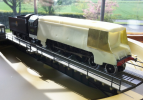
The following images begin with 2010 efforts and end with work this week. Not complete as yet but uncertainty about continuing the project has begun to evaporate. I am in parallel converting a Hornby Series I (black livery 21C7) to a later manifestation in Malachite green with the modified cowling and deflectors and to me the resin kit has to look comparable to the latter conversion.

1690527298782.png

Lead sheet glued inside the casing and illustrating the surgery to append the Hornby cab and buffer beam to the resin kit.

1690528138004.png

Back in 2010 the loco was posed with a Series III tender. Deflectors were cut from brass sheet and subsequently replaced with Albert Goodall etched parts. The resin body requires a fair amount of filling on the cast edges. The sand filler hatches are not in the correct place for the MN but I have compromised on changing that. The Hornby cab requires panelling to be replaced below floor level. The bogie wheels subsequently went off to another project but will be replaced in due course.

There then follows a 13 year hiatus when the project box was opened, contents scrutinised and then closed again. Should I scrap the project in favour of a Hornby product? This week with the prospect of having time to evaluate and answer that question I put the project box in my luggage and set to along with two other projects (21C7 and painting, lining and naming 34021 'Dartmoor').

1690530180991.png
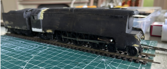
A wash coat of matt black and filling and filing.


1690531404068.png

35008 in the centre, Brunswick Green and lining applied one side. Albert Goodall etched deflectors. Black paint required (I ran out). The addition of the smokebox number plate, lamps and irons, steps, coupling and cylinder drain pipes I think will give the impression / image that I wished for. If I were to do this again I would look at using the Albert Goodall cast hood and smokebox door.

I am encouraged by the progress and results. Perhaps Hornby will produce a Series I with the modified cab in time but I am not counting on it. Part of the encouragement to get this project done is the progress on Lyminster Junction where there is the prospect of 35008 running in the not too distant future. Orient Line will be allotted to haul a lengthy Devon Belle consist and the lead weighting in the casing will definitely be an advantage.
 
4mm Lyminster Junction
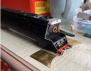
I finally plucked up the courage to take a razor saw to a Hornby Series I Merchant Navy, the black livery 21C7 'Aberdeen Commonwealth. The objective is to forward date the locomotive to a post-War condition in Malachite Green livery with modified front end with deflectors and casing hood. I have found the Harvey book on the Merchant Navy Class invaluable and in there is a helpful side-on picture of the loco with 'Southern' on the tender and the number '35007' in sunshine lettering on the cab. Importantly the cut down of the rear rave on the tender is clear and looks like the rave removal wet down to the very top of the tender tank.

First task was to paint the wheels in Malachite. Second task was to make the casing cuts around the smokebox. Third task was to fit the Albert Goodall casting for the casing hood. The tricky part follows in that the casing around the chimney was altered with the addition of the deflectors. Hornby has this as a solid moulding so the widening has to be achieved very carefully to avoid damaging the chimney. I wrapped it in making tape and then spent several hours with razor saw, drills and files to re-shape that part of the casing and then to insert the case hood.

1690538094982.png

1690538151925.png
The next tasks are to cut down the rear rave on the tender and to prepare the fitment of the etched deflectors. Critical to appearance is to file the top of the casing cut at an angle so it looks like part of the 'joggle' at the joint with the bottom of the deflector.

I need to do more livery research as, if the loco stays as 21C7 and not renumbered to 35007 as seen in the Harvey book, am I OK to keep the '21C7' in sunshine numerals with green shading? Further, was the front of the hood painted green or black as shown in George Heiron's paintings? I am inclined to go for green as the whole ensemble will be very striking.
 
4mm Lyminster Junction
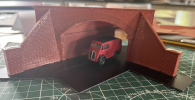
Before donning the wet suit for a week in Wales, I made progress on the layout itself. Following and on-line field trip courtesy of Googlemaps, I put together an under bridge to install through the embankment.

It is made from Finecast components and represents an acute intersection between railway and road. Railings will be installed later A matching bridge portal will be constructed to insert from the other direction through the Woodland scenics high density styrofoam embankment.

I have lain track using DCC legacy bullhead. I have found the Peco Bullhead fishplates to be the best option to use having tried DCC's plates and Peco 'N' gauge fishplates.

1690539203915.png
 

John57sharp

Western Thunderer
My project boxes are a physical manifestation of my tendency to start things off, not have parts to continue, run out of time or drive (mojo) and set a project aside for a while. I keep the project parts in pencil case-sized stackable boxes that means parts, materials and subject loco, coach, wagon or other are in one place. This works reasonably well with my mojo or time constrained way of doing stuff as I draw comfort from the thought that time spent on projects is in effect captured in each project box. Although the stack of project boxes on one hand sits as a monument to a shortage of personal focus or parts, each one also represents and reminds me that my time spent on my hobby is cumulative, that each one represents invested time and each period of activity takes me closer to some conclusion.
This sums up my modelling very well indeed, right down to the comfort, which is very important to me.

Thanks
John
 
4mm Lyminster Junction
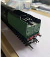
A month on and the primary activity has been on locomotives. That's due to a combination of mojo failure and my work obligations that only allows for short periods which are OK for achieving completion of small jobs that add up to a 'done job'. Firstly I continued with my forward dating of 21C7 from the Hornby wartime black livery version. The rear rave of the tender was cut down guided by a picture of the prototype in Hervey's book. This is relatively simple s the rave appears to be cut down to the top of the tender tank.
1693328696095.png

The next task has been to prepare for the fitment of the Albert Goodall / RT brass smoke deflectors. The location to make cuts around the smokebox front is helpfully marked by Hornby's rivet pattern on the casing - very logical:
1693329305187.png
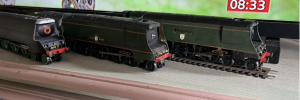
This picture is to illustrate that the fairing is cut down almost to the top of the horizontal sheet afore the firebox door. Again the rivet pattern on the casing corresponds well with the size of the Albert Goodall/RT deflector and the drawings in the Hervey book. The stand-offs provided with the deflector are too long and need cutting back a tad at the rear, preserving the bracket which anchors the deflector to the smoke box front.

Ready now for the second deflector and all the front end detail. The buffer mounted steps are always vulnerable to damage when working on the body as is the case here.

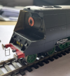
The second project was/is something I wanted to do for some time which was to modify a rebuilt Hornby Merchant Navy principally to see what the effect of changing the Hornby smokebox door out for one by Albert Goodall/RT. I felt the Hornby model did not capture the appearance adequately.

Many moons ago I began a Crownline Merchant Navy kit, determined that this would be my 'tour de force', soldering brass and fettling valve gear. Compensated chassis assembled, tender built, body built, but then all work halted for domestic and work reasons. Then the Hornby MN appeared. So the first mission to produce a 'pride of the line' top link loco stalled.

I looked recently at restarting the exercise but in the intervening years the compensated chassis had locked up meaning disassembly was needed to fix it, and consideration of a Hornby chassis as a quick fix also foundered on the amount of butchery needed on the Crownline body. So that went back in the box for a time when I can prioritise it. However, the Series I tender was prepared for the new project using a Hornby MN starting point. One day, perhaps it will go behind the loco it was built for! However, tender swapping is prototypical.

The work done on the Hornby MN comprised:
1) Remove deflectors and cut off the Hornby smokebox door. Replaced with a cast alternative from Albert Goodall/RT,
2) Fit smokebox door furniture and replace deflectors
3) Fit cylinder drain pipes (also Albert Goodall/ RT),
4) Remove the bogie, reverse it and cut off the coupling housing. This is to improve the front end and to aid fitting of guard irons on the bogie.
5) Fit scale bogie wheels to improve appearance of the front end,
6) Fit brake pull rods by drilling out the shoe and actuating mechanism holes and fitting Peco track pins through them from inside of the chassis to the outside. Drill out the pull rods at the joints with the actuating mechanism and slide over the track pins. Trim and spot glue. They won't now fall off quite so easily!
7) Fit the buffer beam hoses and other details. Glue the route indicator discs in place.
8) Fit the smokebox number and nameplates.

1693332264251.png

1693332371003.png

My opinion is that the front end is much improved compared to the original Hornby product. The form of the original smokebox door is too flat in my eyes. Still detail work to do and then to touch up the paint. I am not enamoured with the smoke deflectors and I can see a change out for brass alternatives in the future. However, for now this will be a good outcome for an early 1960's prime hauler on the layout. Sorry the pictures are not crisp - I don't have the knack with the iPhone camera but I hope the model gives the impression of the change in appearance at the front end, subtle it may be. Certainly, if Hornby announce a re-work of the type, I will not feel driven to acquire one.

Similarly the Crownline loco remains in the 'to do' stack and I still aspire to completing it in the future.
 
Top