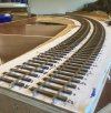
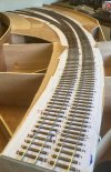
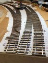
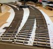
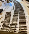
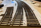
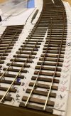
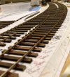
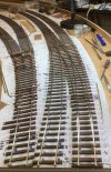
7mm Lochmaben, a new layout.

OzzyO

Western Thunderer
Hi Ozzy,

I am doing something similar at the moment. Are they silver soldered or soft soldered?

Regards,

Ken

Hello Ken,

just soldered with 188deg. solder. As long as your fiddle yard team don't dwell to long soldering them down all should be well.

ATB

OzzyO.
 

OzzyO

Western Thunderer
Hello all,

maybe I should have put these up dates in my last post?
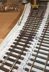
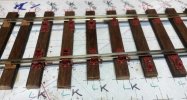
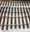
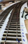
As I mentioned a few posts back I was hoping to get all of the rails into place on the first point on the front of the layout, I did manage to get the rail in place and the chairs stuck down, so just two quick photos before we called it a night.
BB 104.JPG

BB 105.JPG


ATB

OzzyO.
 

OzzyO

Western Thunderer
Hello all,

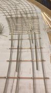
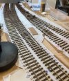
the fiddle yard gang are doing well (not surprising as about 5 of them are involved now). Kev has made a start on the two curved three way points at the entrance to this end of the fiddle yard.
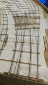
BB 116.jpeg

My first point for the front of the layout done apart from the details, I think that it looks ok. The track on the R/H side is not fixed down.
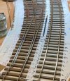
BB 107.JPG

Then I had the fun job (not) of filing up 16 point blades. After I had finished filing the first side of 8 I thought that there must be a better way, so I sat and had a drink and a think. I came up with a plan to use the mill, the first job was to set up the jig in the vice. To do this I had to use the clock to set the part of the top face that I wanted parallel to the table. A bit of rag to clean off but a lot quicker than filling.
BB 108.JPG

Before and after a clean up.
BB 109.JPG

But you always get one naught boy in the play ground, and this was him.

BB 113.JPG

After seeing the headmaster this is what he looked like.
BB 114.JPG

All sixteen blades done, I may have another two pairs to do. But now I've got this sorted not a big problem.
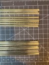
BB 115.JPG

All I have to do now is to try and figure out how to M/C the flat face of the blades!

ATB

OzzyO.
 

OzzyO

Western Thunderer
Hello all,

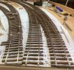
not that much to report at the moment, the fiddle yard boys are working away and getting on with things. The point blades for the two three way points just laid in place.
BB 117.JPG

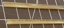
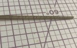
While I was doing the point blades I came up with an idea as the Off the Rails point chairs are a bit tight on the Slater's rail we are using and I have snapped one or two. This was the idea a push cutting broach normally in engineering this sort of tool is puled through the job.
To make it I got a length of rail and mounted it in the point blade filling jig and filed off the bulge at the foot of the rail tapering to full size on both sides, then it was making the cutting edges across the rail using a razor saw one cut going L - R and one cut going R - L until I got to the full sized rail. I gave it a trial last night and it works (not as well as I would have liked) but it is OK and it works. Now I have to get used to how make it work better.
BB 118.JPG
BB 119.JPG
BB 121.JPG

ATB

OzzyO.

PS, Off the Rails do say that the chairs are made for C & L rail, so I don't know if Slater's rail is slightly thicker in the web?
 

simond

Western Thunderer
Ozzy,

how are you holding both rail to mill it?

maybe your broach would cut better if you slotted it on the mill? Lots more work than the razor saw, of course, but you could ensure you have clearance for the “chip” as it’s cut from the chair.

Just hypothesising here, but if you were to plunge-cut the rail with a slot drill from the foot upwards, you could arrange for the cutting edges to be quite sharp. Trouble is, you’d need to use a very small drill to avoid losing the support of the previous “tooth”.
 

OzzyO

Western Thunderer
Ozzy,

how are you holding both rail to mill it?

maybe your broach would cut better if you slotted it on the mill? Lots more work than the razor saw, of course, but you could ensure you have clearance for the “chip” as it’s cut from the chair.

Just hypothesising here, but if you were to plunge-cut the rail with a slot drill from the foot upwards, you could arrange for the cutting edges to be quite sharp. Trouble is, you’d need to use a very small drill to avoid losing the support of the previous “tooth”.

Simond,

Your first question if I'm reading it correctly, is that it's held in the Scale 7 filling jig and I mill one rail at a time but only on one face.

The answer to your second reply is that the time taken to set up the mill to do the cutting would have taken far to long. My smallest Dia. cutter is 1mm, also the amount of "chip" from the resin chairs per cut is minimum for the amount of travel. You have to remember I'm only talking about 1 or 2 thou per side to remove, but as the printed resin is a bit on the brittle side I'd like to go a bit slow and keep the chair in one piece.

The idea in your third reply is very good, but you would be plunge cutting into a rail that is at its Max. 1.6mm (0.062") with a web thickness of 0.6mm (0.025") it would give you some very good cutting edges but the ping factor of the cutters could be very expensive as you would only want to a cutter of about 2 - 2.5mm dia. to get the cutting edge. Then you would have to advance by about 3.5mm to the next 'hole' so the cut would not be that good and the trailing edge of the cut would have to have the rag removed.

ATB

OzzyO.
 

OzzyO

Western Thunderer
Ozzy,
Just hypothesising here, but if you were to plunge-cut the rail with a slot drill from the foot upwards, you could arrange for the cutting edges to be quite sharp. Trouble is, you’d need to use a very small drill to avoid losing the support of the previous “tooth”.

Simond,

I 've had a bit more of a think about how you were saying about making the broach, in the M/C (mill). I think that you would have to use two strips of metal in the web and then plunge down to depth.

But that would then leave you with a parallel rail with some cutting faces, but you would then have to put the two tapered faces on the rail sides so that you can go into the chairs without applying any excess stress to the chairs.

Or you could make the rail to the taper and then make two tapered wedges to suit.

ATB

OzzyO.
 

simond

Western Thunderer
Hi Ozzy,

yes, I think you’d have to temporarily fill the webs whilst you plunged the cutter, or you might not get many edges per slot drill.

Thinking more about it, even if you used a 1mm slot drill, you’d have to cut on alternate sides of the broach-to-be, and you would not have any clearance on the back of cutting faces, well, it would be negative, because the broach itself is a wedge. Indeed, that might explain why your razor-saw version didn’t work as well as you had hoped.

not easy. Sorry not to have had a better idea!

atb
Simon
 

OzzyO

Western Thunderer
Hello all,

the broach is working Ok but not as well I would have liked and it has reduced the ping factor.
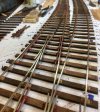
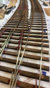
On to the front of the layout, not a lot to show for a couple of weeks work. In these two photos we are looking towards the station, the main line is on the right, the point that you can see is the entrance to the yard.
BB 122.JPG
BB 123.JPG

Then it was time to drop the base board that was nearest to the camera and have a move around. So that the base board at the back became the one at the front of the next photos.
I think that my plan is going to go something like this, from the right hand side rail 1 lay the stock rail over the next BBJ then rail 4 over the BBJ, then rail 5. After that it will be getting the common crossings into place. Then the next sets of stock rails (I hope!). What can possibly go wrong?
BB 124.JPG
BB 125.JPG

Lets see what I get up to tomorrow!!!!!!!!!!!!!!!!

ATB

OzzyO.
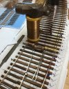
PS the common crossing is not fixed in place.
 

OzzyO

Western Thunderer
Hello all,

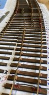
just a quick update on progress. Rail 1 in place and over the BBJ. With the following point chairs in position, P1A1, P1A2, 12 S1 (normal running rail chairs), the check rail chairs and then it's onto a normal running rail. Rail 4 has the check rail chairs in position and the 12 S1 chairs and the P1A2 and P1A1 but not all of them are fixed down yet.
BB 126.JPG

BB 127.JPG

By the end of the night I had got all of the point rail chairs and keys in place on rail 1, you may have noticed that I'm using a brass slide chair as the first of the slide chairs on the points I'm doing this as we still have to fit the droppers that will move the point blades and I did not want to risk melting a slide chair. I have also made a start on some of the point chairs on rail 2.
BB 133.JPG

BB 132.JPG

While I was in my padded room the boys were getting some of the fiddle yard boards ready to be dropped, so a quick photo was in order when it was all nice and clear.
BB 129.JPG

ATB

OzzyO.
 
Last edited:

OzzyO

Western Thunderer
Hello all,

I decided to go to the club on Saturday to have a look at my track laying and get some more rails laid down.
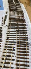
My plan was to get the common crossing (vee from now on) on rail 2 in place and fixed down with the chairs in place. Then to have a look at the vee for rail 3. Setting the vee in place on rail 3 using my track pin hammer and some more weight. You can never have to many track gauges! Think that I may have got the check rail a bit far from the running rail! and on the wrong rail!
BB 134.JPG
BB 135.JPG

While the glue was going off I got rail 2 in place and over the BBJ. All was going well until I removed the weights and seen this.
BB 136.JPG

I had got the stock rail way out of gauge, so it was lets get the chairs off the sleepers. Not to bad a job for the Exactoscale ones just add more solvent and a bit of help form Mr. Swan Morton job done, the printed ones what to do? I knew the solvent would not help as these were stuck down with a type of super glue!
So I decided to just try Mr. Swan Morton very slowly and he worked wonders not one chair broken. So that problem is sort of solved.
BB 137.JPG
BB 138.JPG

ATB

OzzyO.
 

OzzyO

Western Thunderer
Hello all,

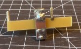
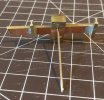
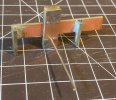
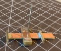
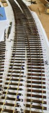
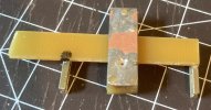
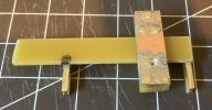
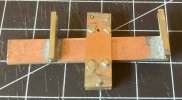
well Last of the summer wine , had electrical Entwistle well we have electrical Edwards and we got talking about fitting the servos for working the points in the fiddle yard (approx. 20), the point tie bars have been drilled by eye so could be a bit out of centre for the operating pin. As the servo can be set to the centre of its travel we came up with this idea, all I to do was make it and make it work.

The first part was made by Kev two bits of rail soldered to a bit of copper clad sleeper, this is to fit between the point blades and the stock rails. Then it was making the sliding bracket also out of copper clad sleeper, I did pin it and glue it together.
BB 149.JPG BB 151.JPG
BB 152.JPG

Then it was how to get the information down to the servo, simple just add a bit of nickel silver rod! No add a nice hard pin and with having the taper to the end it helps to get it into the hole in the servo crank.
BB 153.JPG
BB 154.JPG
BB 155.JPG
BB 156.JPG

All we have to do is to test it and see if it works as we would like.

ATB

OzzyO.
 

OzzyO

Western Thunderer
Hello all,

it's a bit of time since I did an update on the point building (manly because I keep forgetting to take some photos).
The first point of the pair of points for the crossover with all of the track in place.
BB 140.JPG

Getting ready to start on the next part of the crossover, both stock rails are in the rough positions before gauging from the vee. I have to position the check rail chairs and check rails in place alone with some of the point chairs before I can fix them (stock rails) in position. (yes I have seen the kink in the first point pointed [sorry] out to me more on that latter).
BB 141.JPG

Just so you can see the keys been fitted to the chairs (I don't know how the 4mm people do it!) This is before the insertion tabs had been removed, I had a bit of brain fade and forgot to fit the two chairs that are on the sleeper ends (these two are not keyed), before I got going on laying the rail, only option was to cut them to fit around the running rail..
BB 142.JPG

We now have more track on the layout! No it's just a mirror to help me fit the keys in the chairs.
BB 144.JPG

The first of the plain track (closure rail?) in place.
BB 145.JPG
BB 146.JPG

The same point from the toe end with the switch rail in place. Only one and a half points to sort out now, but will I have enough rail to do all of that?
BB 147.JPG

ATB

OzzyO.
 

Phil O

Western Thunderer
Ozzy,

Us 4mm modellers have to thread the chairs onto the rail, before we fit it in place, it can be a right pain, especially if the flash needs clearing between the jaw and key first.
 

OzzyO

Western Thunderer
Ozzy,

Us 4mm modellers have to thread the chairs onto the rail, before we fit it in place, it can be a right pain, especially if the flash needs clearing between the jaw and key first.

Hello Phil O

I also have to thread the chairs onto the rail as well, it is a right PITA but it has to be done.

For some reason I was thinking that Off the Rails did the same chairs with separate keys in 4mm. But I've just had a look and can't see any.

ATB

OzzyO.
 

OzzyO

Western Thunderer
Hello all,

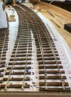
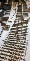
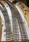
just a quick up date on the points on Lochmaben, the cross over all in place just the tie bars and the cosmetic bits to add. Starting work on the last point in the back ground.
BB 160.JPG

Looking at the cross over from the BBJ, along with the start of the last point. The track is not fixed in place on the last point.
BB 157.JPG

And from the drone.
BB 158.JPG
BB 159.JPG

I must try and remember to take some more photos tomorrow night.

Just placed my order with Ellis Clark trains for 5 pairs of drop head buckeye couplings.

ATB

OzzyO.
 
Top