Lathes and M/C tools.

OzzyO

Western Thunderer
Hello all,

so what do you get for 70 odd quid?

Boring head and arbor, eight boring tools (that could also be used on the lathe) and a block to keep them in (hole are a bit big about 10mm).
post-8920-0-64102900-1438503131_thumb.jpg

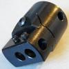
Some close ups of the boring head. You get three mounting holes for the tools, two in the bottom and one across the body. To use the one across the body you would have to grind you own tools,as the boring tools are meant to be used in the bottom two holes.
post-8920-0-41129100-1438503138_thumb.jpg

post-8920-0-57191900-1438503143_thumb.jpg

post-8920-0-22224700-1438503154_thumb.jpg

A close up of the indexing wheel, I've not worked out what the scale is yet, but I think that 1 rev will be 0.5mm (so 1mm off the bore), so per each index 0.02mm (0.0008") off the bore.
post-8920-0-60748800-1438503148_thumb.jpg

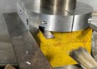
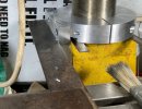
In place on the mill.
post-8920-0-30400700-1438503704_thumb.jpg

Summery,

Good points,

well made and finished, good clear indexes (I may fill them with some black latter on), looks like it will have a good range using the three holes, tools look very good and well ground.

Down side,

arbor could have done with two flats on it to help with tightening the head on, M14X1mm thread was a bit tight (but better than lose), the screw above the index wheel caught on the M14X1mm thread on the arbor, you have to use two Allan keys, one for the slide lock and one for the index, the wooden block could have been a bit better (very minor).

Boring head good value, tools sound a bit dear but not really at £3.07 each.

All in all a nice bit of kit so 8.5 / 10.

OzzyO.

PS. please feel free to ask any questions.

PPS. a link to the full thread over on the other side,
http://www.rmweb.co.uk/community/index.php?/topic/17222-lathes-mc-tools/
 

JimG

Western Thunderer
OssyO,

Can you get your spindle speed slow enough with enough torque in your mill to use the boring head on larger diameter bores?

Jim.
 

ZiderHead

Western Thunderer
For those of us bodgers who haven't used anything more complex than a pillar drill, could you tell us what kind of job you'd use this for?

Ta :)
 

OzzyO

Western Thunderer
OssyO,

Can you get your spindle speed slow enough with enough torque in your mill to use the boring head on larger diameter bores?

Jim.

Jin,

my lowest speed on my mill is 315 rpm. so I don't think that the amount of torque will come in to it. But what size holes do you think that I'm going to be making and what sort of size of cut?

As a point it's OzzyO, it's double Z's.

For those of us bodgers who haven't used anything more complex than a pillar drill, could you tell us what kind of job you'd use this for?

Ta :)

Think of any thing that has a curved base to it like, a smokebox saddle, the base of a chimney, dome or the bore of a set of cylinders that are over the size of any drills or reamers that you have. If you want to see why I bought this bit of kit have a look in my build thread about Anne and me.

If you wanted to get really complex you could also turn a pin on the out-side of a job but you would have to use a tool that has a different cutting geometry to it. It can also be used as a fly cutter that is set to a set diameter to make a slot of a size that you don't have a cutter for (not that I'd tend to use it for that).

HTH

OzzyO.
 

Wagonman

Western Thunderer
Like Ziderhead I've not had any dealings with these wonderful machine tools – when others were learning the rudiments of engineering I was shut away wrestling with Latin irregular verbs – so in a much belated attempt to rekindle my modelling mojo (it's been on sabbatical for several years now) I've bought a lathe!

OK so it's only an old Unimat 3 but that's the about as big as I can accommodate. I have also bought a manual but will almost certainly end up having to pick the brains of the great WT Collective. Stand by...


Richard
 

JimG

Western Thunderer
Jin,

my lowest speed on my mill is 315 rpm. so I don't think that the amount of torque will come in to it. But what size holes do you think that I'm going to be making and what sort of size of cut?

Ozzy,

I was thinking of larger radii - like the seat radius on your smokebox - where you might want to drop into backgear if you were using the head in a lathe.

Jim.
 

Jon Nazareth

Western Thunderer
I used one very similar to this to fly cut the saddle of a chimney for a 3" Fowler traction engine. I think that the diameter of the smoke box was some 7".

Jon
 

Overseer

Western Thunderer
Like Ziderhead I've not had any dealings with these wonderful machine tools – when others were learning the rudiments of engineering I was shut away wrestling with Latin irregular verbs – so in a much belated attempt to rekindle my modelling mojo (it's been on sabbatical for several years now) I've bought a lathe!

OK so it's only an old Unimat 3 but that's the about as big as I can accommodate. I have also bought a manual but will almost certainly end up having to pick the brains of the great WT Collective. Stand by...


Richard
I wouldn't say 'only an old Unimat 3'. They are very accurate and versatile machines that can do everything you will need in 7 mm. The smaller size does mean some things need to be approached differently than with a larger lathe. I haven't tried turning cast iron wheels and wouldn't be keen to, but the Unimat copes well turning down Slaters wheels to S7. The most important thing when using the Unimat is to use sharp tools to suit the material being turned. Commercially available tools may not be sharp and often are not very useful shapes. Grinding your own tools it not difficult once you know how. I could provide some guidance if you are interested.

Try it out with some brass rod to get the feel for it and check everything is lubricated and adjusted properly. Ask any questions and we should be able to help.
 

Wagonman

Western Thunderer
I wouldn't say 'only an old Unimat 3'. They are very accurate and versatile machines that can do everything you will need in 7 mm. The smaller size does mean some things need to be approached differently than with a larger lathe. I haven't tried turning cast iron wheels and wouldn't be keen to, but the Unimat copes well turning down Slaters wheels to S7. The most important thing when using the Unimat is to use sharp tools to suit the material being turned. Commercially available tools may not be sharp and often are not very useful shapes. Grinding your own tools it not difficult once you know how. I could provide some guidance if you are interested.

Try it out with some brass rod to get the feel for it and check everything is lubricated and adjusted properly. Ask any questions and we should be able to help.

Thank you for your very kind offer. I may well take you up on it – when I get some tools!
 

OzzyO

Western Thunderer
Hello all,

I got a new toy for the lathe and mill, this is part of it. Can you tell what it is yet?
IMG_9681.JPG

Now to decide what thread to put this in?

ATB

OzzyO.
 

OzzyO

Western Thunderer
Hello all,

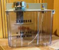
yes it's a coolant tank for a system I'm going to set up, but first I'm going to have some jobs to do on the compressor, drip trays for both the lathe and mill.
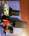
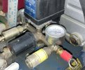
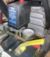
Do you want to see what I get up to? In my building a D. Parkins kit (and some JLTRT coaches as well) I mentioned about the trouble I was having with the compressor in message #46. While I've not been in the best of health I was browsing the Bay of E and came across one of these.
Manifold 01.JPG
Manifold 02.JPG

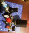
What the old one looks like,
IMG_9691.JPG

I went into the work shop to get some bits for another project that I'm working on downstairs. When I noticed this.
Maifold 03.JPG

One of the fittings had just broken off at the junction between the end of the screw threads and the main body. Compressor to the right.
Manifold 04.JPG

So before I can do any work on any thing that involves the lathe and mill I'm going to have to sort this little lot out. Now I really do hope that the new manifold fits. And my back holds out (fingers crossed, touch wood, sacrifice a few rabbits for their feet) and any good luck charms that I can think of and a few that I'll make up on spec.

I was thinking that I may just fit the electrical to the old manifold, so in a way it has probleby worked out better for me. The new manifold was about £10.50 so not a lot of money, it's just the time and working in a confined space.

ATB

OzzyO.
 

simond

Western Thunderer
I remember the gypsy lady coming to,our house as a kid, selling “lucky rabbit’s feet”.

My dad politely told her to sling ‘er ‘ook, by pointing out that the rabbit itself was not, perhaps, so lucky as she suggested, given that its feet were for sale.
 

OzzyO

Western Thunderer
Hello all,

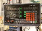
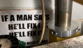
a brake from kits and point operating units, I decided to make a start on this. The digital read out for the mill.
IMG_0111.JPG

The first job apart from fitting the digital readout onto it's mounting brackets.
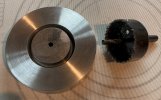
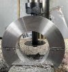
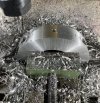
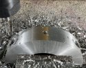
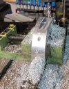
The next part of the job was to make the base ring for fitting the next part to hold the bottom fixing point for the sliding scale. So onto the lathe with a slab of aluminium 4 1/2"dia. and 1" thick, it's 4 jaw chuck time. So in the time honoured way it was face off one face and part of the edge, then drill a hole for the centre of the hole saw then cut the hole to about halfway then turn it around and do it all again.
Then bore the hole to size approx. 60mm. Still using the 4 jaw chuck turn the outer Dia.

All this showed up the head stock bearings are in need of replacing, I've had look on flea bay but no good. The numbers of the bearings are 46107D (single row angular ball bearing), 46108D ( single row contact ball bearing) 103G & 104G ( single row angular ball bearings 104G single direction). The bearing that's the ball bearing thrust bearing I want to replace it with a tapered thrust bearing.
IMG_0115.JPG

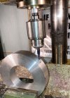
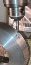
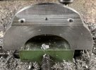
The next job was to mill a flat for the drill to start on.
IMG_0118.JPG
IMG_0120.JPG

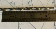
Then to drill the holes 5mm first using a normal length drill. Then to get the length of the hole it was to use a extra long drill.
IMG_0121.JPG

The extra long drill.
IMG_0125.JPG

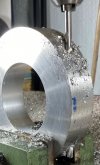
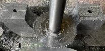
Now the fun starts splitting the ring in half, this was with a .8mm saw that was flat ground not like you normally get hollow ground so you get a thou or two clearance in the middle. I made a new arbour but I made it about 1/2" short so I didn't have as much in the chuck as I would have liked, I had about 2mm clear above the top of the ring.
IMG_0126.JPG

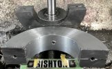
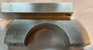
And the ring is in two halves, the faces need a run over with a facing cutter about 0.2mm should clean them up.
IMG_0128.JPGIMG_0129.JPG
More to follow.

ATB

OzzyO.
 

OzzyO

Western Thunderer
Hello all,

the second part of making the bottom ring for the glass scale to fix to.
The first half ring with the joint face cleaned up. You can just make out a witness mark on the L/H side, it looks like a 1,2,3 triangle.
IMG_0131.JPG

The first job was to drill out the counter bores for the fixing screws for the two halves, this is also showing the mess that aluminium makes with the work that's going on. The centre hole is for a small grub screw, just to make sure that the scale cannot move in relation to the column.
IMG_0130 A.JPG
Just a bit closer to the job.
IMG_0130.JPG

Setting up the second half of the ring.
IMG_0132.JPG

Not a bad effort 0.01mm (or 0.00039").
IMG_0133.JPG

Milling out the step for the beam for the bottom of the scale. I've been taking cuts of 6mm deep and 7mm wide with a 8mm rippa cutter, apart from the sort of cuts you can take with these cutters is the swarf just small chips not the pins you get with a normal end mill. I don't know what the feed rate was as I don't have a power feed. I was using neat cutting oil, more to clean up.
IMG_0135.JPG

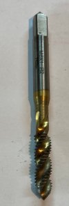
The step finished with the two holes drilled for the screws for the extension piece, for tapping the holes I used a tap (m6) with a helix in the power drill then it was just finish tapping the bottom of the holes.
IMG_0136.JPG

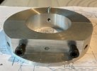
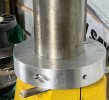
The two halves fastened together the pointed screw is the grub screw to lock the rings in place.
IMG_0137.JPG

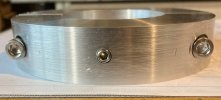
Showing the screws in place but not tightened up.
IMG_0140.JPG

A couple of photos showing the position of the ring. It's about 1mm above the yellow casting that holds the vertical column.
IMG_0141.JPGIMG_0142.JPG

Just got the bracket to drill and fix in place. After I've M/C a bit more of a step in the bracket ring. Do I use Loctite??

ATB

OzzyO.
 
Last edited:

OzzyO

Western Thunderer
Hello all,

onto the last leg for the bottom ring.
But first the type of tap I used in the drill to cut all the threads in the M6 holes.
IMG_0146.JPG

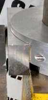
The bottom ring with the extra cut out showing, this is in case the hole for mounting the glass scale is going to be at the edge of the ring.
IMG_0149.JPG

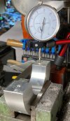
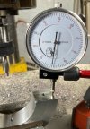
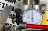
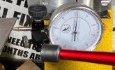
Setting up the square using a D.T.I.
IMG_0150.JPG

I'll take that 0.02mm (0.00078") that's over 5" of travel on the cross slide. Maybe I should have just clocked up the mounting bar? Doing it this way I could just use feeler gauges to see how I was doing.
IMG_0151.JPG

The bottom ring in place, the feelers that you can see work out to be 0.045"
IMG_0152.JPG

Getting ready to start setting the bottom ring.
IMG_0154.JPG

IIRC by the time I'd tapped the ring about I got it to 0.0015" over 100mm. the mounting bracket for mounting the scale is about 25-30mm long so any misalignment should be OK.IMG_0155.JPG
IMG_0156.JPG

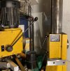
Something has gone wrong with the mill!
IMG_0157.JPG

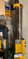
The brackets for scale are going to fit on.
The top one the small yellow flat to the left of the black panel.
The bar on the bottom ring for the bottom bracket.
The reading head will go on the large yellow block, it will/should go just below the large black panel. I'm going to have to make some packing piece's to pack it out from the body.
Then I've got to figure out how to fit the swarf protector. This one doesn't get that much swarf frown at it.
IMG_0158.JPG

The next bit is fitting the scale and looking at how to fit the longitudinal one. The one that's going to be a bit of a problem is the cross slide as some/all of the faces are just cast.

ATB

OzzyO.
 
Last edited:

Rob Pulham

Western Thunderer
Hi Paul,
I fitted a DRO to my mill late last year, I took photos but haven't written it up yet. I will do so on separate thread so that those who are interested get a couple of different views on how to tackle it on different machines.
Thankfully mine didn't require the level machining that yours did.
 
Top