Elmham Market in EM

James Spooner

Western Thunderer
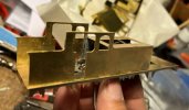
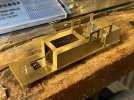
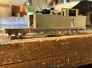
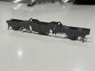
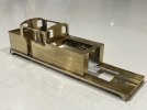
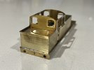
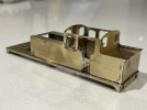
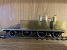
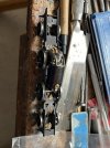
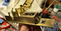
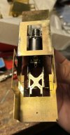
I just wanted to test that the chassis, in particular the motor and gearbox mount, would actually fit inside the body envelope. Accordingly I built the footplate assembly and made a start on the tank and cab structure. All seems to be well so far (photos taken before I had cleaned up the body components).

Nigel


IMG_3844.jpegIMG_3846.jpegIMG_3847.jpeg
 

James Spooner

Western Thunderer
More progress this evening on the body and ensuring it and the chassis fit snugly together. Firstly the holes in the footplate were matched up to those on the chassis spacers (these weren’t quite in the right place so new holes were drilled). The bunker former has been made up and soldered on to the sides, then the combined tank/cab/bunker unit was soldered to the footplate unit and finally this evening the chassis was bolted on to ensure it all fits. Photos attached.

Nigel


IMG_3863.jpegIMG_3862.jpeg
 

James Spooner

Western Thunderer
Not much modelling done last weekend (and very little time enjoying the glorious weather either!) as I was helping steward ExpoEM both days. I did take some locos and stock out for a spin on the test track and have a video of the G5 and push pull set, as well as one of a Gibson J15 and freight. Both attached.

Nigel


Dave Holt

Western Thunderer
Hi Nigel.
We manage to avoid meeting once again - I was there on Saturday.
I noticed that the inner tracks on the circuit, where your locos are running, were marked as "P4" and the outer two as "EM". Was that incorrect or were you using the P4 tracks?
Running very nicely irrespective of gauge.
Dave.
 

Bulldog3444

Member
Hi Dave,
I think that it is only the inside track which is P4.
I used the two outer tracks to test a couple of locos we were running on Otterford (EM).

Sorry that I didn’t get a chance to see your locos on the test track, Nigel.
Ian
 

AJC

Western Thunderer
Sorry to have missed you on Sunday, Nigel - @Dave Holt EM locos run perfectly well on P4 plain track (indeed, you can use P4 track as gauge-widened track in EM which Yeovil MRJ did 30 odd years ago - not 100 percent sure they meant to, but it's just fine!).

Adam
 

James Spooner

Western Thunderer
It sounds as though we were all missing each other! Yes, the outer three tracks are all EM and only the innermost is P4 and, yes again, with no points on the innermost circuit it is entirely possible to happily run EM locos and stock on the P4 track. For most of the weekend the loop next to the P4 one was set up for DCC running, hence me using that track.

Nigel
 

James Spooner

Western Thunderer
I’ve been plugging away at the F6 over the last couple of evenings. I have primed the chassis and will probably give it a top coat tomorrow (then set it all up with wheels, motor etc over the weekend).

The body is slowly coming together. A couple of evenings hard soldering bending and filing has got me cab sides and front/back with details and a bunker rear. Looking at the instructions I think I move on to the boiler next so that’s a good place to stop for the evening.

The cab as provided is pretty basic inside. Despite rummaging through my library, I haven’t come across any images of the inside of an F6 cab (or, for that matter, the very similar F4/5). Does anyone out there know of any photos so I can add detail before soldering the cab on?

Some photos attached.

Nigel

IMG_3904.jpegIMG_3906.jpegIMG_3907.jpegIMG_3908.jpeg
 

Paul Tomlinson

Western Thunderer
Nigel, just had a quick look at the John Gardner drawings from the GERS - L11 includes the cab interior for F4/F5 in final condition (there may be others).
 

LarryG

Western Thunderer
I popped into Minnfford Station's lay-bye to make a phonecall a couple of weeks ago and I'm pretty sure I saw the new Fairlie in the station. It was the dark colour that caught my attention. A lady I know has relations all over that area so I often call in Portmadoc for a Latte and teacake. A family member in Blaenau gave us the heads up of the £10 ride from there to Tan-Y-Bwlch, but we couldn't make it.
 
Looking good James.
I use 145C solder for everything, with liquid flux (Carrs Yellow - or homemade 12% phosphoric accid)), the only exception being 70C solder for whitemetal parts (with 145C for pre-tinning any brass or N/S to whitemetal parts will be fixed)
I have used 180C and 240C along with 145C for complex assemblies, where the intent is to avoid previously soldered parts falling off as you add more parts on. I have found the higher temperature 240C solder more difficult to work with (and harder on the soldering iron tips) and of late just use 145c for everything - if you are in and out quick, and don't dwell too long, everything stays together as it should.

My singular soldering challenge to date has been affixing the LMS tender side laminates / overlays on my Brassmasters kits. I have a 75W iron, and use 145C solder, but struggle to get enough heat into the pieces to get the solder really flowing (despite pre-tinning). I can get there, but not without some minor distortion to the over-laminates when viewed against the light.
 

James Spooner

Western Thunderer
I popped into Minnfford Station's lay-bye to make a phonecall a couple of weeks ago and I'm pretty sure I saw the new Fairlie in the station. It was the dark colour that caught my attention. A lady I know has relations all over that area so I often call in Portmadoc for a Latte and teacake. A family member in Blaenau gave us the heads up of the £10 ride from there to Tan-Y-Bwlch, but we couldn't make it.
Yes, almost certainly James Spooner as the other two are either maroon or tomato soup colour…. It is a sublime engine to drive!

Nigel
 

James Spooner

Western Thunderer
Looking good James.
I use 145C solder for everything, with liquid flux (Carrs Yellow - or homemade 12% phosphoric accid)), the only exception being 70C solder for whitemetal parts (with 145C for pre-tinning any brass or N/S to whitemetal parts will be fixed)
I have used 180C and 240C along with 145C for complex assemblies, where the intent is to avoid previously soldered parts falling off as you add more parts on. I have found the higher temperature 240C solder more difficult to work with (and harder on the soldering iron tips) and of late just use 145c for everything - if you are in and out quick, and don't dwell too long, everything stays together as it should.

My singular soldering challenge to date has been affixing the LMS tender side laminates / overlays on my Brassmasters kits. I have a 75W iron, and use 145C solder, but struggle to get enough heat into the pieces to get the solder really flowing (despite pre-tinning). I can get there, but not without some minor distortion to the over-laminates when viewed against the light.
Thanks Darren. I generally use 183C solder for all of the main joints and often Carr’s 188 solder paste for much of the smaller bits. If soldering whitemetal I use some 100C. Somehow, in reverse to you, I have never got on with 145C, only using it to tin brass before adding a whitemetal component with low melt.

Nigel
 

James Spooner

Western Thunderer
It’s been a while since I posted and that is partly because I am on the run up to my retirement and am spending more evenings than is good for my cholesterol and waistline going to dinners, but also partly because I have hit a bit of a problem with the chassis and have been spending time figuring things out.

I built the chassis according to the instructions and primed, then painted it. I then wheeled it and trial fitted the body. At that point I realised that the whole flexible chassis design has a basic flaw in that it rocks around the central pivot on the driving wheels. Various options came to my mind from, at one extreme, scrapping the chassis and starting with a scratchbuilt one, through trying to retrofit a Mike Sharman flexichas unit, to springing the pony trucks with enough force (and then stacking the centre of the body with a shed load of lead - which isn’t a problem as there is quite a lot of space in the tanks) to keep the loco level but still have flexibility in the operation.

After much cogitation I decided on the last route, mainly because the cross members in the chassis would need to be hacked around or even cut out to retrofit a flexichas design. It may well come to that at some point in the near future but I thought I would take it in baby steps.

I have therefore soldered two springs to press the pony trucks down (and in the process stabbed myself with the soldering iron- fortunately with only a slight scar on my finger) and have moved on to the coupling rods. These seem a little tight in places so I’m working through easing the tight spots to get a free running coupled chassis before I add the brakes etc and turn my attention back to the body. A couple of photos are attached, the first showing the tilt to the back and the second showing the springs soldered in place.

Nigel

IMG_3974.jpegIMG_3987.jpeg
 

simond

Western Thunderer
Nigel,

if I’ve understood correctly, the loco has two pony trucks, and two driving axles. The driving axles are both suspended by see-saw compensation beams, one attached to each frame. If so, it appears that the designer intended springs on the pony trucks (which is what you’re doing), or failed to arrange some other kind of support in pitch.

I think a very simple solution would be to fix one of your compensation beams to its frame. This will provide pitch stability. The other compensation beam will do it’s stuff, and keep all four drivers on the rails. Three point compensation. Your pony trucks then only need to stay on the track, light springing or weight.

Initially, I’d just tighten the pivot screw & nut, but once it’s running nicely and level, you could pop a pin through beam and frame, or just a blob of solder, of course.

atb
Simon
 

James Spooner

Western Thunderer
Nigel,

if I’ve understood correctly, the loco has two pony trucks, and two driving axles. The driving axles are both suspended by see-saw compensation beams, one attached to each frame. If so, it appears that the designer intended springs on the pony trucks (which is what you’re doing), or failed to arrange some other kind of support in pitch.

I think a very simple solution would be to fix one of your compensation beams to its frame. This will provide pitch stability. The other compensation beam will do it’s stuff, and keep all four drivers on the rails. Three point compensation. Your pony trucks then only need to stay on the track, light springing or weight.

Initially, I’d just tighten the pivot screw & nut, but once it’s running nicely and level, you could pop a pin through beam and frame, or just a blob of solder, of course.

atb
Simon
Simon,

That’s brilliant! I like your thinking and will give that a crack. Many thanks - that shows the benefit of fora like WT!

atb

Nigel
 

James Spooner

Western Thunderer
There should be a hole in the beam with a corresponding one in the chassis you can use. Or at least there is one on mine

G
Yes, the beams are bolted inside the frames and at the moment are slightly loose to allow the hornblocks to rise and fall within certain tolerances. My understanding of Simon’s suggestion is that I tighten one of those bolts up to fix the drivers on one side and let the other side still pivot, thereby giving three point suspension and keeping the loco longitudinally level.

Cheers

Nigel
 

simond

Western Thunderer
Exactly.

Is there another hole in one of the beams, and a matching hole in one of the frames? Maybe only small, for a bit of wire?

That would indicate that the kit designer thought of it before me :)
 
Top