Approximately forty years ago I purchased a small paperback contains photos of Edinburgh’s railways. It included a grainy photo with gently flowing p.way and absolutely reeked with atmosphere. At that time, all that would/could have been replicated as a model would have been the visible bit of track from the photo.
A copy of an old (1880's?) 25" OS map of west central Edinburgh purchased in the 90's rekindled interest, and provided details that were indistinguishable in the photo. It also provided an indication of the sort of size required, which wasn’t available. It was clear that if ever to be built in 4mm, there would need to be a degree of compromise.
A house move early in the millenium resulted in a 17ft double garage. 12ft for scenic model, 4-5 foot for the fiddleyard or to bend lines through 90degrees to the fiddleyard, including 1ft for errors... Things were looking up!
Compromise would be required by straightening the station ever so slightly, minor repositioning of a couple of buildings and using a retaining wall that separated the two halves of the station as the scenic edge. There were enough photos on the internet, I naively thought, that would help me create the atmosphere I wanted, but there were still some challenges that would need to be overcome. Rather than create an absolute scale model, this would be an interpretation of the location. This would be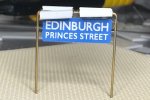
Ok, the squint lamp housing is slightly overdone…
I don’t have a layout plan as such, but the OS map covering the area can be found here NLS Maps. The model, at the beginning, covered from the Morrison Street bridge to part way down the trainshed. The then unfinished control panel is below should anyone prefer to use that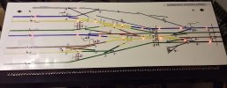
So why Princes St. Really it is a modellers dream. Large engines on big and small trains. Tank engines on fast and local services. Four coach trains not uncommon. DMU services in its later days. Nearly all the later motive power is available rtr, as is coaching stock that give a fair representation of the train formations. And as for the charismatic buildings. With one or two exceptions, they’re big! Approximately 120 train movement, excluding light engine or empty stock in a 24 hr period, there’ll be plenty to do!
After a visit from colleagues from the Scottish Region Study Group, a minor issue was noticed. Not really with the layout, but with us. As we get older, we stop growing up, and many of us start growing out. With only 12ft of scenic frontage, you were limited to 5 people in front of the layout. Eventually, like Topsy, the decision was taken to expand the layout and conveniently the Grove Street bridge now acts as the end of the scenery.
The original version had an estimated build of seven years. Since work started, much more valuable information has become available through the internet. There are black holes though, like a side view of the water tank. I have a very distant end view, and a view looking down on it, but no side view. Edinburgh Council planning portal had an application for double glazing for a Morrison St building, including dimensions of a window from which the height of a building was checked, to discover my guesstimate was too high. Fortunately, errors are normally spotted during a models build, although in respect to the buildings on the Morrison St bridge, some partially build structures had to be scrapped and replaced to keep the proportions between buildings correct to photos.
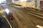
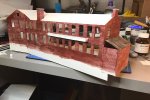
This is approximately 7’6” of the original scenic area. The buildings with the Sweetex stair wells had to be rebuilt after discovering they were too high.
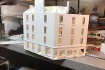
The building on the west corner of Morrison Street and Gardeners Crescent, showing the side not so obvious from the front of the layout. Apart from being cleaned, and modern shop signs fitted, the external remains relatively unchanged.
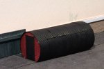
Every so often it’s nice to have a small structure. An old Sweetex dispenser covered with Ambis Engineering corrugated sheeting.
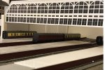
The train shed screen. This was always going to be the biggest challenge. Eventually built to this stage with seven laminations cut by a Silhouette cutter.
the train shed walls are the Mk2 version, the originals being @ 2cm too high, which made the opening obviously out of proportion.
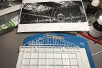
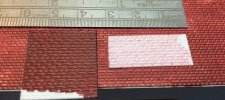
And finally for this post, some proving models for part of the trainshed roof. Before I develop the roof further, the internal trussing needs to be started
Cheers
Ian
A copy of an old (1880's?) 25" OS map of west central Edinburgh purchased in the 90's rekindled interest, and provided details that were indistinguishable in the photo. It also provided an indication of the sort of size required, which wasn’t available. It was clear that if ever to be built in 4mm, there would need to be a degree of compromise.
A house move early in the millenium resulted in a 17ft double garage. 12ft for scenic model, 4-5 foot for the fiddleyard or to bend lines through 90degrees to the fiddleyard, including 1ft for errors... Things were looking up!
Compromise would be required by straightening the station ever so slightly, minor repositioning of a couple of buildings and using a retaining wall that separated the two halves of the station as the scenic edge. There were enough photos on the internet, I naively thought, that would help me create the atmosphere I wanted, but there were still some challenges that would need to be overcome. Rather than create an absolute scale model, this would be an interpretation of the location. This would be

Ok, the squint lamp housing is slightly overdone…
I don’t have a layout plan as such, but the OS map covering the area can be found here NLS Maps. The model, at the beginning, covered from the Morrison Street bridge to part way down the trainshed. The then unfinished control panel is below should anyone prefer to use that

So why Princes St. Really it is a modellers dream. Large engines on big and small trains. Tank engines on fast and local services. Four coach trains not uncommon. DMU services in its later days. Nearly all the later motive power is available rtr, as is coaching stock that give a fair representation of the train formations. And as for the charismatic buildings. With one or two exceptions, they’re big! Approximately 120 train movement, excluding light engine or empty stock in a 24 hr period, there’ll be plenty to do!
After a visit from colleagues from the Scottish Region Study Group, a minor issue was noticed. Not really with the layout, but with us. As we get older, we stop growing up, and many of us start growing out. With only 12ft of scenic frontage, you were limited to 5 people in front of the layout. Eventually, like Topsy, the decision was taken to expand the layout and conveniently the Grove Street bridge now acts as the end of the scenery.
The original version had an estimated build of seven years. Since work started, much more valuable information has become available through the internet. There are black holes though, like a side view of the water tank. I have a very distant end view, and a view looking down on it, but no side view. Edinburgh Council planning portal had an application for double glazing for a Morrison St building, including dimensions of a window from which the height of a building was checked, to discover my guesstimate was too high. Fortunately, errors are normally spotted during a models build, although in respect to the buildings on the Morrison St bridge, some partially build structures had to be scrapped and replaced to keep the proportions between buildings correct to photos.

This is approximately 7’6” of the original scenic area. The buildings with the Sweetex stair wells had to be rebuilt after discovering they were too high.

The building on the west corner of Morrison Street and Gardeners Crescent, showing the side not so obvious from the front of the layout. Apart from being cleaned, and modern shop signs fitted, the external remains relatively unchanged.

Every so often it’s nice to have a small structure. An old Sweetex dispenser covered with Ambis Engineering corrugated sheeting.

The train shed screen. This was always going to be the biggest challenge. Eventually built to this stage with seven laminations cut by a Silhouette cutter.
the train shed walls are the Mk2 version, the originals being @ 2cm too high, which made the opening obviously out of proportion.

And finally for this post, some proving models for part of the trainshed roof. Before I develop the roof further, the internal trussing needs to be started
Cheers
Ian

 I’ll leave that to those much more skilled in the smaller scales than I am. In the same space you could probably include the associated goods yards and be a fair way towards Dalry Rd shed.