DM Workbench

David Mylchreest

Active Member
I haven't done any modelling for years having become very discouraged and lacking in motivation to do anything really during the lockdown. Interest has been picking up however and this High Level 03 Chassis build will, fingers crossed, get me going.
I bought the kit at Scaleforum 2022 and got the wheels from Alan Gibson at the same time. It's going to be P4 and battery radio controlled when it's finished.
The first task was to read through the destructions after downloading them of course. I did have a few issues as I'm not too sure about the Fig Numbers even after reading through several times
The first task is to remove the steps and the sand boxes from the body which I acquired several years ago from Richards Spares at a show.P1001557.JPG
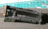
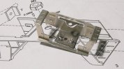
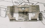
The second was to remove the steps component from fret and fettle it. The areas marked on black marker pen have to be removed for a model which features the recessed front steps.
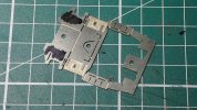
P1001560.JPG
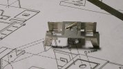
The next step is to drill the holes with a 0.5mm drill. Not all these holes are fully etched through, so I used a mini drill.
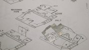
P1001562.JPG
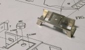
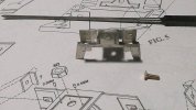
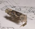
The component shown next to the instructions
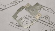
P1001563.JPG
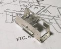
And on it's own.
I stopped there as my eyes, which don't have much depth of field nowadays, were getting tired
 
Last edited:

David Mylchreest

Active Member
A little bit more over the last few days ...565 Front Steps.JPG
The front steps folded up
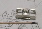
567 Front Steps.JPG
You have to locate the two halves of the fold with 0.5mm wire which is supplied in the kit. I bent the wire over to stop it falling out!
570 Front Steps.JPG
I soldered from underneath because it seemed to be the easier thing to do
571 Front Steps.JPG
Excess wire snipped off and solder cleaned up.
I'm getting the impression that there is a limit of the number of photos you can upload per post. To be continued in my next.
 
Last edited:

daifly

Western Thunderer
I'm getting the impression that there is a limit of the number of photos you can upload per post. To be continued in my next.
There is, but you're nowhere near it. It was 15, and may still be. There is also a limit on photo size. If you're attempting to load a photo that's too big (over about 2Mb), it will probably be rejected.

Dave
 

David Mylchreest

Active Member
572 Front Steps.JPG573 Front Steps.JPG
The centre hole was enlarged to M2 clearance (which really means here that the screw was a floppy fit) by using a broach.
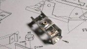
574 Front Steps.JPG
Sorry about quality of the photo here. The M2 nut was soldered on using the cocktail stick to hold it down, the solder cleaned up and an M2 tap run through to clean up the thread.
There is often a request for advice about holding taps. For small sizes like M2 and smaller (or their BA equivalents) I use a pin vice not a tap wrench as I'm less likely to impart a sideways thrust with a pin vice and so break the tap.
576 Front Steps.JPG
The steps are added. I generally use a 1mm solder bit because it limits the amount of solder I can put on a joint and so the amount I have to clean up. I prefer to solder from the inside but here there isn't an inside here because both sides can be seen. I haven't done this sort of thing before (or at least I haven't made a success of it), for this joint I added flux on the outside of the steps and soldered from the outside. The solder followed the flux and created a small fillet on the inside of the step. I was pleased with that :). Then I cleaned up the surplus on the outside.
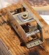
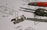
More to follow.
 

David Mylchreest

Active Member
651 Front Steps.JPG
Continuing with the front steps. This photo shows my attempt to solder the step detail onto the top step. Not a good idea but to be fair the destructions do mention that you can use an adhesive instead. I think I'll learn the lesson and do that for the other steps, perhaps the primer paint might do the trick.
578 Rear Steps.JPG
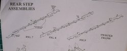
So, a start on the rear steps. At first it's easy enough, just a simply fold up and soldering an M2 nut652 Drawing For Rear Steps Frame.JPGThis is the drawing for the rear step frame. It turns out that the 03s had the frame twisted but the 04s don't, but it is quite a characteristic of the 03. See the photo below which I couldn't get to embed.
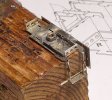
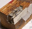
The destructions do say that this is quite difficult to do and get right and they are absolutely right, I think I made a mistake in trying it, it would have been better not to.657 Rear Steps Twist Outcome.JPG658 Rear Steps Twist Outcome.JPG
It hasn't helped that I over-twisted one side and broke it necessitating a solder repair which are never entirely satisfactory. But I now think it would have been better not to try, way beyond my skill set and I really don't know how this could be done and have both twists identical which must be the desired outcome. Hey ho.662 Rear Steps.JPG
This rather out-of-focus photo shows the current state with the lower bar soldered to the rear buffer beam.
Not an altogether satisfactory couple of hours work, very disappointing in fact, proving yet again that I'm no craftsman :(
Onward and Downward!
 
Last edited:
Top